Ship or pick up from our office.
Product Sheet PDF
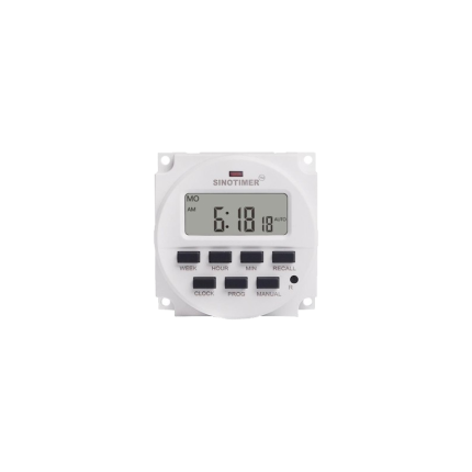
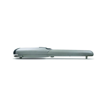
Double swing gate opener –VDS EGO110
More information about the swing gate openers:
WHAT ARE THE DIFFERENT TYPES OF SWING GATE MOTORS?
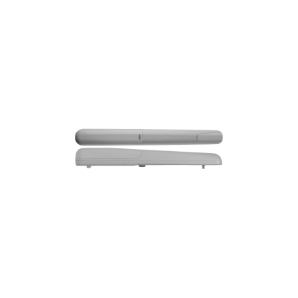
1- Articulated Arm for Swing Gate Operators
How do automatic gates work with articulated swing gate motors?
An
articulated arm electric gate opener uses a two-part arm with an ‘elbow’ joint to connect the motor to the gate.
This arm protrudes from the gate motor body, so there has to be room for the arm to move as the driveway gate opens and closes.
This type of electric gate opener is easier to install than other types, thanks to the geometry of the arm system.
They can be slightly more expensive than other gate motors, but they open and close automated gates quickly.
Many homeowners like discrete gate automation systems, and articulated arm motors can be more obvious when installed. However, many have the control system built into one of the motors.
These motors for automatic gates are mounted on the inside of gates so they’re not seen from the outside of closed gates.
In the event of power failure or mechanical breakdown, articulated arm motors can normally be released manually from outside the gate with an optional cable release system.
All articulated arm gate operators are electric gate motors that can be either 120VAC or 24VDC.
All 24V and some 120V versions have obstacle detection. This means that the gates stop moving and some even reverse when they come into contact with an object during operation.
Articulated arm gate automation systems can be the best choice where each electric gate opener is mounted on a large gate pier or pillar.
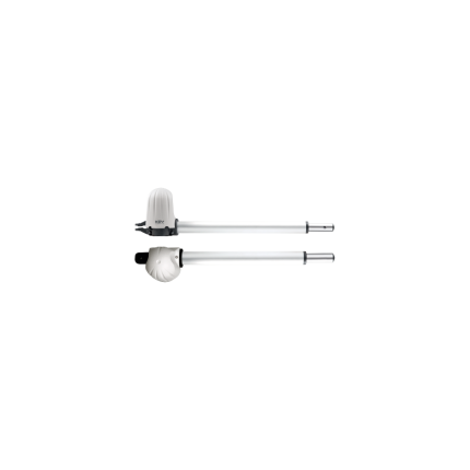
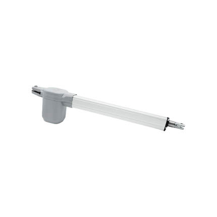
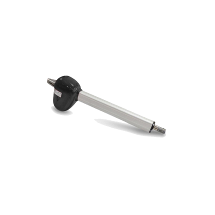
2- Ram And Linear Screw Automatic Swing Gate Openers
Ram gate automation motors push and pull a piston mounted on the gate.
Linear screw electric motors for gates use an electric motor to rotate the gate mounting along a threaded shaft.
Both types of electric gate motors are slim and don’t need a lot of space to operate.
However, this advantage does mean that they require careful alignment during installation.
Manual release systems are only available from inside the driveway gate.
A ram or linear screw type of motor for automatic gate control is attached to the gate at one end and the gate pillar or post at the other end.
Ram motors can be hydraulic or driven by electric motors, but all require a separate control box.
As with articulated arm motors, 120Vac, and 24Vdc, you can buy versions with obstacle detection for safer operation.
Additionally, heavy-duty versions of each type of electric gate opener are available that will operate larger gates with leaves up to 7m long.
These electric gate openers can be the best gate automation solution when price is important. Their simpler design and operation can make them a cost-effective solution compared to other types of electric gate motors.
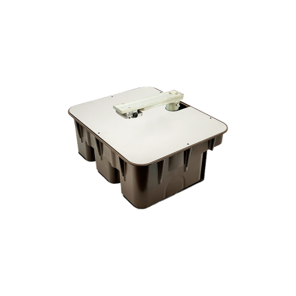
3- Underground Swing Gate Operators
Many Canadian homeowners choose underground gate automation motors because they are very discreet.
This is because each
underground gate opener is hidden under the hinge end of each swing gate
.
But how do automatic gates work when they’re opened and closed by hidden underground motors?
During installation, a carefully positioned hole must be dug to house a foundation box for each underground gate opener.
The housing for each underground electric gate motor needs sufficient drainage to prevent the motors from sitting in water, or they will fail.
Underground electric gate motors don’t need a lot of space to operate and can be installed on the inside or back of gate pillars.
They are usually only installed behind gate pillars when the gates must open more than 90 degrees, so that the post or pillar does not obstruct the gates.
With the addition of a 180-degree gate opener, your gates can open much wider than 90 degrees.
This is an optional chain drive system for driveways that bend around behind the gate pillars.
If the gate only opened to 90 degrees, it could block part of the driveway.
But a 180-degree gate opener system means that it can keep going past 90 degrees, so it doesn’t block the driveway.
Normally, underground automation of gates is the most expensive solution, but they are almost invisible.
It is possible for the most powerful underground gate opener to open and close a swing gate up to 5m long.
Underground motors for automatic gates can be manually released from outside the gate.
These types of gate motors can be either hydraulic or electromechanical.
A separate control box is required, and 120VAC and 24VDC versions with obstacle detection are available.
Underground gate opener installation is not simple, and it should always be installed by professional electric gate engineers.
Underground gate automation could be the best style for you if you want a discreet, almost invisible electric gate motor installation and you have the budget for this more expensive option.


Reviews
There are no reviews yet.