• +1 (778) 384 2800
  • info@retcc.ca
  • Sample Gate Designs
  • Auxiliary Links
Wishlist
Fast Estimate
Fast Estimate
Royal Gates Royal Gates
  • Home
  • About us
  • Shop
  • Services
    • Driveway Gate
      • Swing Gates
      • Sliding Gate
      • Boom barrier gate
    • Gate Operators
    • Access Control Systems
  • Price
  • Projects
  • Blogs
  • Contact us
Search
0 Compare
1 item $44.60
Menu
Royal Gates
Fast estimate
1 item $44.60
“Digital programmable ON/OFF relay” has been added to your cart. View cart
Relay Mini PCB 5-Pin 10A
Click to enlarge
Home Accessories Relay Mini PCB 5-Pin 10A
Programmable timer relay
Programmable timer relay $40.80
Back to products
PIR Infrared Sensor – wireless
PIR Infrared Sensor – wireless $129.90

Relay Mini PCB 5-Pin 10A

$3.25

Ship or pick up from our office.

Relay Mini PCB 5-Pin 10A

A Relay Mini PCB 5-Pin 10A is a compact, electromechanical switch designed to be mounted directly onto a printed circuit board (PCB). It uses a small control voltage to switch a larger current, making it useful for isolating control circuits from power circuits or for switching higher-power loads with a low-power signal.

Key Features and Specifications

  • Mini: This indicates its small physical size, making it suitable for applications where space is limited.
  • PCB: This means it’s designed for Printed Circuit Board mounting. Its pins are typically configured to be soldered directly into holes on the PCB.
  • 5-Pin: These five pins usually consist of:
    • Two pins for the coil: These are where the control voltage is applied to energize the coil and activate the relay.
    • Three pins for the contacts: These typically include a common (COM) pin, a normally open (NO) pin, and a normally closed (NC) pin.
  • 10A: This is the maximum current rating that the relay’s contacts can safely switch. It means the relay is capable of handling up to 10 amperes of current through its switched contacts.

How It Works

A relay fundamentally operates on the principle of electromagnetism. When a small electrical current flows through the coil of the relay, it generates a magnetic field. This magnetic field attracts an armature, causing a set of electrical contacts to either close (making a connection) or open (breaking a connection).

  • Normally Open (NO): The contact is open when the coil is de-energized and closes when the coil is energized.
  • Normally Closed (NC): The contact is closed when the coil is de-energized and opens when the coil is energized.


Common Applications

These relays are widely used in various electronic circuits and systems, including:

  • Automotive applications: For controlling lights, motors, and other accessories.
  • Home automation: Switching lights, appliances, and HVAC systems.
  • Industrial control: In PLCs (Programmable Logic Controllers) and other control panels.
  • Appliance control: In washing machines, refrigerators, and microwave ovens.
  • DIY electronics projects: Where low-power signals need to control higher-power devices.
Compare
Add to wishlist
Category: Accessories Tags: driveway gates, gate automation, gate motor, Gate opener, gate operator, relay
Share:
  • Description
  • Additional information
  • Reviews (0)
  • Shipping & Delivery
Description

Relay Mini PCB 5-Pin 10A

*DC 12-24 Volt

*NC/NO

*10 Amp

A mini PCB 5-pin 10A relay is a small, electronic switch that can be mounted directly onto a printed circuit board (PCB) and is designed to control a circuit with a 10-amp current capacity.

It has five pins and is often used in applications where a low-power control circuit needs to switch a higher-power load. 

Key features and characteristics:
  • Miniature size:

    Designed for compact PCB layouts, making it suitable for space-constrained applications. 

  • 5-pin configuration:

    Typically includes pins for coil power (for control) and a single-pole, double-throw (SPDT) contact arrangement (for switching). 

  • 10-amp rating:

    Capable of switching circuits with a maximum current of 10 amps. 

  • PCB mountable:

    Designed to be soldered directly onto a PCB for a secure and space-efficient connection. 

  • SPDT (Single Pole, Double Throw):

    This contact configuration allows the relay to switch between two circuits. When the coil is energized, it moves the contact from one position to another, effectively acting as a switch. 

  • Applications:

    Widely used in various applications, including automotive systems, industrial controls, and electronic devices, where a low-power signal is used to switch a higher-power circuit. Examples include controlling lights, motors, or other electrical components. 

  • Coil voltage:

    Requires a specific coil voltage (e.g., 5V, 12V, 24V) to activate the electromagnet and switch the contacts. 

  • SPST (Single Pole, Single Throw):
    Some 5-pin relays may also be SPST (Single Pole, Single Throw), which means they have one input and one output and can only be either ON or OFF. 
Additional information
Weight 0.01 kg
Dimensions 3 × 2 × 2 cm
Reviews (0)

Reviews

There are no reviews yet.

Be the first to review “Relay Mini PCB 5-Pin 10A” Cancel reply

Your email address will not be published. Required fields are marked *

Shipping & Delivery

Shipping & Delivery

We will process your online order and ship it to you immediately via Canada Post.

You may also like…

Programmable timer relay
Compare

Programmable timer relay

Accessories
$40.80

Ship or pick up from our office.

Programmable timer relay

A programmable timer relay is an electronic device that combines the functions of a timer and a relay, allowing users to set specific time delays for switching electrical circuits on or off. Essentially, it acts as an automated switch that operates based on pre-programmed time intervals. This enables the automation of various processes and equipment across a wide range of applications. How it Works Programmable timer relays incorporate internal circuitry (often microcontrollers or digital logic chips) that allow for precise timekeeping and control. Here's a general overview of how they function:
  1. Control Signal: The programmable timer relay receives an input or "trigger" signal, which initiates the timing process. This signal can come from a switch, sensor, or another control device.
  2. Timing Mechanism: Once the signal is received, the internal timing mechanism begins to count down or up based on the programmed parameters.
  3. Delay Period: During this delay, the relay's contacts remain in their initial state (either normally open or normally closed).
  4. Contact Switching: Once the programmed delay period elapses, the relay's contacts change state, either closing to allow current to flow or opening to interrupt it.
  5. Maintaining State & Resetting: The relay maintains its new state until the input signal is removed, or a reset function is triggered. Programmable relays offer various timing modes, such as:
    • On-delay: The relay activates after a set delay once the input signal is applied.
    • Off-delay: The relay deactivates after a set delay once the input signal is removed.
    • Interval: The relay activates for a set period and then deactivates.
    • Cyclic: The relay repeatedly alternates between on and off states for specified durations.
Users can typically configure these timing modes and sequences through a digital interface, often with an LCD or LED display for easy setup and monitoring.   Applications Programmable timer relays are incredibly versatile and are used in numerous applications to enhance efficiency, save energy, and improve safety:
  • Industrial Automation: They control the sequencing of machinery, conveyor belts, pumps, and other equipment in manufacturing processes, ensuring precise timing and preventing system overloads.
  • Lighting Control: Used in homes, commercial buildings, and street lighting to turn lights on and off at specific times or based on ambient light levels, optimizing energy consumption and security.
  • HVAC Systems: Regulate fan operations, compressor cycles, and defrost cycles in heating, ventilation, and air conditioning systems to maintain desired temperatures and reduce energy use.
  • Security Systems: Implement delays for door locks, alarm systems, and surveillance cameras, allowing for controlled access and scheduled activation/deactivation.
  • Pump Control: Manage water pumps, sewage pumps, and sump pumps, ensuring they operate only when needed, which conserves water and prevents pump damage.
  • Home Automation: Automate various household appliances like irrigation systems, washing machines, and dishwashers.
  • Vehicle Systems: Control functions like intermittent windshield wipers and turn signals.
  Advantages Programmable timer relays offer several benefits over traditional, non-programmable timer relays or complex PLC (Programmable Logic Controller) systems for certain applications:
  • Versatility and Customization: They can be programmed for various timing functions and sequences within a single unit, offering great flexibility for diverse applications.
  • Energy Savings: By automating on/off cycles and ensuring equipment runs only when necessary, they help reduce energy consumption and costs.
  • Increased Efficiency: They enable automated control of equipment and processes, improving overall operational efficiency and reducing the need for manual intervention.
  • Reduced Components and Wiring: By integrating multiple timing and switching functions into one device, they can replace several individual timers and relays, simplifying wiring, reducing component inventory, and saving space in control panels.
  • Cost-Effectiveness: For simpler automation tasks, they offer a more economical solution compared to full-fledged PLCs.
  • Ease of Use: Many programmable timer relays feature user-friendly digital interfaces or software, making them relatively easy to configure without requiring extensive programming knowledge.
  • Precise Time Control: They offer high temporal precision, with delays ranging from milliseconds to several hours.
  • Troubleshooting: Integrated displays often provide alarm messages and I/O status, simplifying troubleshooting.
Add to wishlist
Add to cart
Quick view
Relay 5-Pin 40A
Compare

Relay 5-Pin 40A

Accessories
$23.85

Ship or pick up from our office.

Relay 5-Pin 40A

A 5-pin 40A relay is an electromechanical switch commonly used in automotive and other applications. It allows a low-power electrical signal to control a higher-power circuit. The "5-pin" refers to the number of terminals it has, and "40A" indicates that its contacts can safely handle a maximum current of 40 amps. How it Works A relay essentially functions like a remote-controlled switch. It has two main circuits:
  • Control Circuit (Coil): This low-power circuit energizes an electromagnet inside the relay.
  • Switched Circuit (Contacts): This high-power circuit is controlled by the electromagnet, either opening or closing connections to a device.
Here's a breakdown of the pins:
  • Pins 85 and 86: These are the coil terminals. When a small current (typically 12V DC in automotive applications) is applied across these pins, it creates a magnetic field.
  • Pin 30: This is the common terminal for the switched circuit. It's usually connected to the main power source (e.g., battery) through a fuse.
  • Pin 87: This is the Normally Open (NO) contact. When the relay coil is energized, pin 30 connects to pin 87, allowing current to flow to the connected device.
  • Pin 87a: This is the Normally Closed (NC) contact. When the relay coil is not energized, pin 30 is connected to pin 87a. When the coil is energized, this connection breaks.
The presence of both Normally Open and Normally Closed contacts makes a 5-pin relay a Single Pole Double Throw (SPDT) switch, meaning it can switch power between two different circuits. Why Use a Relay? Relays are crucial for several reasons:
  • High-Current Control: They allow you to control high-current devices (like headlights, fuel pumps, or cooling fans) with a low-current switch. This protects the sensitive, smaller switches from being damaged by excessive current.
  • Reduced Voltage Drop: By placing the relay closer to the high-current device and power source, you can use shorter runs of heavier gauge wire for the high-current circuit, minimizing voltage drop and ensuring the device receives adequate power.
  • Safety: They isolate high-current circuits from the passenger compartment, enhancing safety.
  Common Applications 5-pin 40A relays are widely used in:
  • Automotive: Headlights, fog lights, horns, fuel pumps, electric cooling fans, power windows, central locking, and various aftermarket accessories.
  • Industrial Control: Switching motors, solenoids, and other heavy-duty equipment.
  • General Purpose: Any application where a low-power signal needs to control a higher-power circuit.
Wiring Diagram Example A common wiring configuration for a 5-pin relay is:
  • Pin 85: Connect to ground (-).
  • Pin 86: Connect to the positive (+) side of your control switch. When this switch is activated, it provides power to the coil.
  • Pin 30: Connect directly to the positive (+) terminal of your battery, always through an appropriately sized fuse.
  • Pin 87: Connect to the positive (+) terminal of the device you want to power when the relay is activated (Normally Open connection).
  • Pin 87a: (Optional) Connect to a device you want to power when the relay is not activated (Normally Closed connection).
This setup ensures that a small current from your control switch safely triggers the relay, which then handles the larger current required by the connected device.
Add to wishlist
Add to cart
Quick view
Diode 1N4007
Compare

Diode 1N4007

Accessories
$1.85

Ship or pick up from our office.

Diode 1N4007

The 1N4007 is a very common and versatile silicon rectifier diode. It's part of the 1N400x series of general-purpose diodes, with the "7" indicating its specific voltage rating. Key Characteristics
  • Rectifier Diode: Its primary function is to convert alternating current (AC) into pulsating direct current (DC) by allowing current to flow in only one direction.
  • High Reverse Voltage Rating: The 1N4007 can withstand a peak repetitive reverse voltage (VRRM​) of 1000V. This makes it suitable for high-voltage applications.
  • Average Forward Current: It can handle an average forward current (IF​) of 1 Ampere (1A).
  • Forward Voltage Drop: When conducting in the forward direction, it has a relatively low forward voltage drop (VF​) of approximately 0.7V to 1.1V. This voltage drop represents the power lost within the diode.
  • Surge Current Capability: It can handle a non-repetitive peak surge current (IFSM​) of up to 30A for short durations, which is useful for handling initial power-on surges.
  • Package Type: It typically comes in a DO-41 axial-lead package, which is a small, cylindrical plastic package with leads on both ends.
  • Operating Temperature Range: It operates reliably over a wide temperature range, typically from -55°C to +175°C.
How it Works Like all diodes, the 1N4007 is a PN-junction device. It consists of a P-type semiconductor and an N-type semiconductor joined together.
  • Forward Bias: When a positive voltage is applied to the anode (P-side) and a negative voltage to the cathode (N-side), the diode is forward-biased. If the applied voltage exceeds the forward voltage drop (around 0.7V for silicon diodes), the diode conducts, allowing current to flow from anode to cathode.
  • Reverse Bias: When a negative voltage is applied to the anode and a positive voltage to the cathode, the diode is reverse-biased. In this state, the diode acts like an open switch, blocking current flow. The 1N4007 is designed to withstand up to 1000V in this reverse-biased state before breaking down.
Common Applications The 1N4007's robust characteristics make it popular in a wide range of electronic circuits, including:
  • Rectifier Circuits:
    • Half-wave and Full-wave Rectifiers: Essential for converting AC power from the mains (like in household appliances) to DC power for electronic devices.
    • Bridge Rectifiers: Used to convert the entire AC waveform into pulsating DC, achieving more efficient rectification.
  • Power Supplies: Used for rectifying the AC input in power supply units to provide DC voltage to various components.
  • Voltage Protection:
    • Reverse Polarity Protection: Prevents damage to circuits if the power supply is connected with incorrect polarity.
    • Freewheeling Diodes (Flyback Diodes): Protect sensitive components from voltage spikes generated by inductive loads (like relays, motors, and solenoids) when their magnetic field collapses.
    • Voltage Spike Suppression: Helps to suppress transient voltage spikes that can occur due to switching events or lightning, safeguarding delicate electronics.
  • Inverters and Converters: Used in various power conversion circuits.
  • Current Flow Regulation: Can be used in simple current limiting or flow control applications.
Due to its high reverse voltage rating, the 1N4007 is often a go-to choice when a general-purpose rectifier diode is needed, especially in circuits that might experience higher voltages.
Add to wishlist
Add to cart
Quick view
Diode 1N5408
Compare

Diode 1N5408

Accessories
$4.45

Ship or pick up from our office.

Diode 1N5408

The 1N5408 is a common general-purpose rectifier diode. It's designed to allow electric current to flow primarily in one direction, making it crucial for converting alternating current (AC) to direct current (DC). Think of it like a one-way valve for electricity. It belongs to the 1N540x series of power diodes, known for their ability to handle relatively high current and voltage. Here are its key characteristics and common uses: Key Features
  • High Reverse Voltage Rating: It can withstand a maximum repetitive reverse voltage (VRRM​) of 1000V. This means it can block high voltages when current tries to flow in the "wrong" direction.
  • High Forward Current Capacity: It's rated for an average rectified forward current (IF(AV)​) of 3 Amperes (A). This indicates it can handle a significant amount of current flowing through it in the correct direction.
  • High Surge Current Capability: The 1N5408 can handle non-repetitive peak forward surge currents (IFSM​) of up to 200A for short durations, protecting circuits from sudden power spikes.
  • Low Forward Voltage Drop: When conducting, it has a relatively low forward voltage drop (VF​) of approximately 1.0V to 1.2V at its rated current. A lower voltage drop means less power is lost as heat.
  • Standard Recovery: It's a "standard recovery" diode, meaning its switching speed is relatively slow compared to fast recovery diodes. This makes it suitable for power rectification at lower frequencies (like 50/60 Hz AC).
  • DO-201 Package: It typically comes in a DO-201 axial-leaded package, which is a through-hole component with leads extending from both ends, allowing for easy mounting on circuit boards.
  • Wide Operating Temperature Range: It can operate and be stored in a wide temperature range, typically from -65°C to +175°C.
  Applications The robust nature of the 1N5408 makes it a staple in various electronic designs:
  • Power Supplies and Rectifiers: This is its primary application. It efficiently converts AC input voltage into pulsating DC, which can then be smoothed by capacitors to provide a stable DC output for electronic devices. This includes full-wave and half-wave rectifier circuits.
  • Battery Chargers: Used to convert AC wall power into DC for charging batteries.
  • Voltage Regulation Circuits: Helps in maintaining a stable output voltage by rectifying current.
  • Protection Circuits: Its ability to block reverse current makes it useful for reverse polarity protection, preventing damage to sensitive components if the power supply is connected incorrectly.
  • Freewheeling Diode: Used in inductive circuits (like those with relays or motors) to provide a path for stored energy to dissipate when the current is switched off, preventing voltage spikes that could damage other components.
  • Voltage Doubler Circuits: Can be used in circuits designed to effectively double the input voltage.
Add to wishlist
Add to cart
Quick view
Digital programmable ON/OFF relay
Compare

Digital programmable ON/OFF relay

Accessories
$44.60

Ship or pick up from our office.

Digital programmable ON/OFF relay

A digital programmable ON/OFF relay is an electronic switch that can be programmed to turn electrical devices on or off at specific times or intervals. It combines the fundamental switching functionality of a traditional relay with the advanced timing and control capabilities of a digital timer or microcontroller. This allows for automated control of various devices and systems without constant human intervention. How it Works At its core, a digital programmable ON/OFF relay operates similarly to a standard relay by using a small electrical current to control a larger electrical circuit. However, the "digital programmable" aspect introduces a sophisticated timing mechanism.
  1. Digital Interface: Unlike mechanical or analog timer relays with physical dials, digital programmable relays feature an LED or LCD display and a keypad or buttons for programming. This allows users to set precise ON/OFF times, durations, and sequences.
  2. Microcontroller-Based: Most digital programmable relays use a microcontroller to manage the timing and control logic. This internal "brain" keeps track of time and executes the programmed instructions.
  3. Timing Functions: These relays offer a wide range of timing functions, including:
    • On-delay: The relay turns on after a preset delay once activated.
    • Off-delay: The relay turns off after a preset delay once deactivated.
    • Interval timing: The relay stays on for a specific duration after activation.
    • Cyclic operation: The relay repeatedly cycles ON and OFF at set intervals.
    • Astronomic timing: Some advanced models can turn devices on/off based on sunrise and sunset times by calculating the solar position.
    • Photocell integration: Others may include light sensors to activate based on ambient light levels.
  4. Memory Retention: Many programmable relays can store settings in memory even after a power interruption, ensuring that the programmed schedule is not lost.
  Key Features and Advantages
  • Programmable Timing: Offers precise control over when devices turn on and off.
  • Automation: Reduces the need for manual operation, leading to increased efficiency.
  • Energy Savings: Allows for optimization of energy usage by ensuring devices are only active when needed.
  • Flexibility and Versatility: Can be configured for a wide array of applications due to various timing modes.
  • Compact Design: Often more compact than systems using multiple hardwired timers and relays.
  • Ease of Use: User-friendly interfaces for setting up programs.
  • Reliability: Many are solid-state, meaning they have no moving parts, which increases durability and reduces noise compared to electromechanical relays.
Applications Digital programmable ON/OFF relays are highly versatile and found in numerous applications across various sectors:
  • Home Automation: Controlling lighting, appliances, or other devices based on a preset schedule (e.g., security lights, garden irrigation).
  • Industrial Automation: Managing machinery, conveyors, pumps, motors, and other equipment in factories or manufacturing facilities.
  • Building Management Systems: Automated control of HVAC systems (heating, ventilation, air conditioning), lighting (e.g., streetlights turning on at dusk), and security systems.
  • Commercial Applications: Used in vending machines, amusement equipment, and commercial appliances.
  • Agriculture: Controlling irrigation pumps or greenhouse lighting.
  • Security Systems: Activating alarms or security lights at specific times or in response to sensors.
Add to wishlist
Add to cart
Quick view
Relay Mini PCB 8-Pin 1A
Compare

Relay Mini PCB 8-Pin 1A

Accessories
$7.65

Ship or pick up from our office.

Relay Mini PCB 8-Pin 1A

A Relay Mini PCB 8-Pin 1A is a small, electronic switch designed to be mounted directly onto a Printed Circuit Board (PCB). It has eight pins for connections and its contacts can safely switch a maximum current of 1 Ampere (1A).   Key Characteristics
  • Miniature Size: The "Mini" in its name indicates its compact dimensions, making it suitable for circuits where space is limited.
  • PCB Mountable: It's designed for through-hole soldering onto a PCB, integrating seamlessly into electronic designs.
  • 8-Pin Configuration: These pins serve various purposes, including connecting the coil (which activates the relay) and the switch contacts (which control the electrical load).
  • 1A Current Rating: This is the maximum current that can safely flow through the relay's contacts when they are closed.
  • Coil Voltage: The relay's coil operates on a specific DC voltage (e.g., 3V, 5V, 12V, 24V). Applying this voltage to the coil creates a magnetic field that mechanically opens or closes the contacts.
  • Contact Configuration: Many 8-pin mini PCB relays are DPDT (Double Pole, Double Throw), meaning they have two sets of contacts, each with both normally open (NO) and normally closed (NC) positions. This allows for versatile switching operations.
  • Isolation: Relays provide electrical isolation between the control circuit (coil) and the load circuit (contacts), enhancing safety and preventing interference.
Applications Mini PCB relays like the 8-pin 1A version are widely used in various electronic devices and systems where a low-power signal needs to control a higher-power circuit. Some common applications include:
  • Remote Control Systems: Used to switch power to devices based on signals from a remote.
  • Communication Equipment: For routing or switching signals in telecommunications and data networks.
  • Automatic Control Systems: In automation processes to control motors, lights, or other actuators.
  • Household Appliances: Found in various home electronics to manage power to different components.
  • Automotive Systems: Employed in vehicles to control functions like lights, locks, and windows.
  • Instrumentation and Measurement Devices: For precise signal routing and control in sensitive equipment.
Add to wishlist
Add to cart
Quick view
Delay relay 0.5 Sec - AC 24 V to AC 24 V
Compare

Delay relay 0.5 Sec – AC 24 V to DC 12 V

Accessories
$62.15

Ship or pick up from our office.

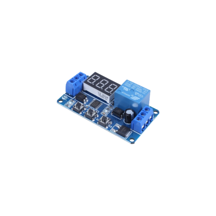
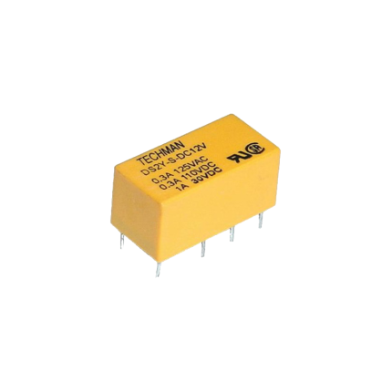
Delay relay 0.5 Sec - AC 24 V to DC 12 V

A "delay relay 0.5 Sec - AC 24 V to DC 24 V" is a time delay relay that is designed to:
  • Operate with a control voltage of 24 volts, which can be either Alternating Current (AC) or Direct Current (DC). This dual compatibility (AC/DC 24V) is a key feature, as many relays are specific to one type of current.
  • Introduce a delay of 0.5 seconds before its contacts change state. This delay can be an "on-delay" (contacts close/open after 0.5 seconds when power is applied) or an "off-delay" (contacts remain closed/open for 0.5 seconds after power is removed), or other timing functions depending on the specific relay's design.
  • Switch or control a separate circuit, which may be a 24V DC circuit. The "AC 24V to DC 24V" in the description refers to the relay's input power compatibility (it can be powered by either 24V AC or 24V DC) and its output capability (it's often used to control 24V DC loads). It is not a direct AC to DC converter for the load it's switching, but rather indicates its flexible control voltage. The relay itself doesn't convert the power; it merely switches it on or off after a delay. If the controlled circuit specifically requires DC, the relay's contacts would simply switch the 24V DC power to that circuit.
Essentially, it's a versatile timing device used in control systems.   Purpose of Time Delay Relays Time delay relays are crucial in various applications where precise timing of electrical events is required. They serve to:
  • Prevent false triggering: A brief fluctuation in voltage or a momentary signal might cause immediate activation in a standard relay. A short delay (like 0.5 seconds) can prevent such nuisance activations.
  • Create timed sequences: In automated processes, certain steps may need to occur in a specific order with set delays in between. For example, a delay relay could ensure one motor starts before another or that a safety purge cycle completes before a furnace ignites.
  • Control motor starts/stops: They can be used for "soft starting" motors, gradually increasing voltage to reduce inrush current, or for ensuring a motor has fully stopped before another action begins.
  • HVAC systems: They prevent "short cycling" of compressors, which can damage the unit, by introducing a delay between successive starts.
  • Lighting control: Ensuring lights stay on for a set period after activation (e.g., in stairwells) or controlling emergency lighting.
  • Security systems: Providing a brief delay before an alarm triggers, allowing authorized personnel to disarm the system.
Types of Time Delay Relays While the "0.5 Sec" refers to the specific delay, time delay relays come with various functions:
  • On-delay (Delay on Make): The most common type. The contacts change state only after the set time delay has elapsed after the control voltage is applied.
  • Off-delay (Delay on Break): The contacts change state immediately when the control voltage is applied, but only return to their original state after the set time delay has elapsed after the control voltage is removed.
  • Interval: The contacts change state immediately when the control voltage is applied, and then return to their original state after the set time delay.
  • Repeat Cycle: The relay continuously cycles between on and off states with specific time delays as long as the control voltage is applied.
In the case of a "delay relay 0.5 Sec", it would likely be an on-delay or interval type, but the exact function would need to be confirmed from the specific model's datasheet.   AC/DC 24V Compatibility The "AC 24 V to DC 24 V" part primarily indicates the coil voltage compatibility of the relay. Many modern time delay relays are designed to accept a wide range of input voltages, including both AC and DC, within a specified range (e.g., 24V AC/DC). This offers flexibility in wiring and application, as the relay can be integrated into systems powered by either AC or DC at that voltage level. It's important to distinguish that this relay itself is not a voltage converter (like a power supply that converts AC to DC). Instead, it's a switching device. If the circuit you are trying to control requires DC and your power source is AC, you would need a separate AC to DC power converter (like a power supply unit) to provide the 24V DC to your load, which the relay's contacts would then switch.
Add to wishlist
Add to cart
Quick view

Related products

Dual swing gate opener –HiGate HGSW950
Compare

Dual swing gate opener –HiGate HGSW950

Gate Automations, Dual Swing Gate Operators
$994.55

Ship or pick up from our office.

Dual swing gate opener –HiGate HGSW950

A dual swing gate opener is a motorized system designed to automatically open and close a double swing gate, which consists of two gate panels that meet in the middle.
Each gate panel has its own opener mechanism, allowing them to swing open in opposite directions simultaneously. This setup is common for driveways and other entry points where a wider opening is needed without requiring a single, longer gate. 
Here's a more detailed explanation:
  • Dual Swing Gates:
    These gates have two leaves or panels that swing open, typically inward or outward, to create an opening. 
  • Dual Opener Mechanisms:
    Each leaf of the gate is equipped with its own opener mechanism, which is usually an arm that pushes or pulls the gate. 
  • Synchronized Movement:
    The two opener mechanisms are designed to work together, opening and closing the gate leaves in a coordinated and synchronized manner. 
  • Applications:
    Dual swing gate openers are commonly used for driveways, parking lots, and other areas where a wide opening is needed and a single gate might be too large or impractical. 
  • Benefits:
    They offer space efficiency as they require less space to swing open compared to a single, long gate. They can also provide a more elegant and sophisticated look to the entrance. 
Add to wishlist
Add to cart
Quick view
Keypad access control K140C101
Compare

Keypad access control K140C101

Access Control
$117.80

Ship or pick up from our office.

Keypad access control K140C101

*Rain Shield Cover *Waterproof Version *EM/ID card/tag reader *Backlight *DC 12 V *Shock resistance *1000 Users *Anti-vandal Metal shell *Doorbell button
Add to wishlist
Add to cart
Quick view
Swing gate opener -VDS MP110
Compare

Single swing gate opener –VDS MP110

Gate Automations, Single Swing Gate Operators
$863.55

Ship or pick up from our office.

Product Sheet PDF

Single swing gate opener –VDS MP110

*Suitable gate weight: Maximum 200 Kg Included: *1 x Electromechanical arm *1 x Main control board *1 x Waterproof box *2 x Remote controls *1 x Manual release key *1 x Safety Sensor
Add to wishlist
Add to cart
Quick view
swing gate opener -VDS RG24
Compare

Dual swing gate opener -VDS RG24

Gate Automations, Dual Swing Gate Operators
$2,177.95

Ship or pick up from our office.

Product Sheet PDF

Dual swing gate opener -VDS RG24

*Suitable gate weight: Maximum 500 Kg (Per leaf) Included: *2 x Electromechanical motor *2 x Foundation box *1 x Main control board *1 x Waterproof box *2 x Remote control *2 x Manual release key *1 x Safety sensor
A double swing underground gate opener is a type of automated gate system designed for double swing gates, where the gate is split into two separate panels that meet in the middle.
The opener mechanism is installed underground, making it virtually invisible and aesthetically pleasing. This dual swing gate opener -VDS RG24 setup allows for a shorter swing radius for each gate leaf compared to a single-panel swing gate. 
Here's a more detailed explanation:
  • Double Swing Gates:
    These gates consist of two gate panels that swing open independently, usually meeting in the middle of the opening. This design is often used for wider driveways or when a single, large gate would be impractical or aesthetically undesirable. 
  • Underground Installation:
    The gate opener mechanism (including the motor and related components) is placed in a foundation box installed below ground level, typically at the hinge point of the gate. 
  • Aesthetics and Space:
    This type of opener offers a cleaner, more discreet look, as the mechanics are hidden from view. It also allows for a shorter swing radius for each gate leaf, which is beneficial in spaces with limited clearance. 
  • Operation:
    The opener receives a signal, usually from a remote control or other access control system, which activates the motor. The motor then rotates a lever or arm connected to the gate, causing it to swing open or closed. 
  • Dual Gate Compatibility:
    Double swing gate openers typically require two gate motors, one for each gate leaf. 
  • Safety Features:
    Many underground gate openers include safety features like limit switches to control the start/stop speed and travel of the gate, as well as manual release mechanisms for emergency situations. 
Add to wishlist
Add to cart
Quick view
Wireless Keypad Access Control KW200
Compare

Wireless Keypad Access Control KW200

Access Control
$127.80

Wireless Keypad Access Control KW200

Wireless keypad access control systems replace traditional keys with a digital PIN code entry for building access, eliminating the need for physical keys and enhancing security.
These systems often include features like remote management via smart devices, audit trails of access events, and integration with other security systems like intercoms. 
Here's a more detailed breakdown:
Core Functionality:
  • Keyless Entry:
    Users enter a unique PIN code into a keypad to unlock a door or gate. 
  • Wireless Communication:
    The keypad communicates wirelessly with a receiver or controller, eliminating the need for extensive wiring. 
  • Remote Management:
    Many systems allow administrators to manage access permissions, view audit trails, and adjust settings remotely via a smartphone app or computer. 
  • Integration:
    Some systems can integrate with intercoms, surveillance cameras, and other security components for a more comprehensive solution. 
Key Features:
  • PIN Codes: Users are assigned unique PIN codes for entry. 
  • Proximity Cards/Fobs: Some systems also support access via proximity cards or fobs for users who prefer that method. 
  • Audit Trails: The system can record and store data about who accessed the door, when, and how, providing a valuable security record. 
  • Weatherproof and Durable: Many outdoor keypads are designed to withstand harsh weather conditions and vandalism. 
  • Backlit Keypads: Backlit keypads make it easier to use the system in low-light conditions. 
Types of Wireless Keypad Access Control:
  • Stand-Alone Systems: These systems are self-contained and don't require connection to a central system. 
  • Integrated Systems: These systems are part of a larger access control or building management system. 
  • Wired and Wireless Hybrid: Some systems combine wired and wireless components for added flexibility. 
Benefits:
  • Enhanced Security: Eliminates the risk of lost or stolen keys.
  • Increased Convenience: Users don't need to carry keys.
  • Improved Auditability: Tracks access events for security monitoring.
  • Remote Management: Allows for easy administration and control. 
Add to wishlist
Add to cart
Quick view
Camera Gate controller
WiFi & Camera Gate/Door controller
Compare

Camera Gate Controller

Access Control
$240.50

Ship or pick up from our office.

Camera Gate Controller

● Universal gate opener/garage door opener phone remote control and 1080P Full-HD outdoor surveillance camera, all-in-one!
  • By using the Camera Gate controller realtime monitor, open and close your door openers remotely using your smartphone from anywhere, any time!
● Features 1080p resolution full high definition CMOS sensor and infrared IR LED, the wireless camera is designed for ultra-sharp clear images and monitor in complete darkness. The 24/7 live video display on your smartphone with the FREE Linkcraft APP ensures your garage or gate is safe and secure. No worry about the status of the door. ● The Camera Gate Controller works with all Gate Openers, and is compatible with most gate openers/garage door openers with External Receiver which is sold separately.
  • Multi-users monitor and control, share your WIFI camera and gate remote access with family and friends. Up to 50 cameras can be added to our APP, and you can take pictures and record videos for your gate or garage on your phone. IP44 Weatherproof - This camera is perfect for outdoor use, and works well under rough weather like storms and snow.
  • Universal smartphone remote control for gate opener/garage door opener / various household appliances / industrial devices and 1080P Full-HD outdoor surveillance camera, all-in-one!
  • Real-time monitor and control your devices using your smartphone from anywhere, any time!
  • Typical applications include opening and closing your door openers, lights, automatic feeders, water pump, and spray system remotely.
  • Features 1080p resolution full high definition CMOS sensor and infrared IR LED, the wireless camera is designed for ultra-sharp clear images and monitors in complete darkness.
  • 24/7 live video display on your smartphone with the FREE Linkcraft APP greatly ensures safety and security.
  • No worry about the status of the door or the device.
  • The wire in the controller works with most gate openers/garage door openers / various electrical equipment.
  • Multi-users monitor and control, share your WIFI camera, and remote access with family and friends.
  • Up to 50 cameras can be added to our APP, and take pictures and record videos for your device on your phone.
  • IP44 Weatherproof - This camera is perfect for outdoor use, and works well under rough weather like storms and snow.
  • Features relay output whose max contact is up to 15A/120VAC & 10A/30VDC, two modes of toggle click and self-hold are selectable.
  • You can set a timer in self-hold mode to adjust the working time of the device.
  • Add up to 128GB micro SD card (optional, SD card NOT included), the video is to be recorded day and night.
  • Easy-to-follow manual is included for quick setting up.

A camera gate controller is a system, often part of an access control system, that combines a camera with the ability to control gate or door access.

It allows residents to see and communicate with visitors at the gate before granting access. This technology enhances security by providing visual verification and remote control of entry points. 
How it works:
  • Camera:
    A camera, often with features like night vision and high resolution, captures video of the gate area. 
  • Communication:
    The system typically includes a way for residents to communicate with visitors, often through two-way audio. 
  • Remote Control:
    Residents can remotely unlock the gate or door through a mobile app or other interface. 
  • Integration:
    Some systems integrate with other smart home or property management systems. 
Key Features:
  • Remote Access: View and control the gate from anywhere with an internet connection. 
  • Visual Verification: See who is at the gate before granting access. 
  • Two-way Audio: Communicate with visitors. 
  • Security Alerts: Receive notifications for motion or other events. 
  • Integration Options: Some systems can integrate with other smart home or access control systems.
Add to wishlist
Add to cart
Quick view
Swing gate opener -Royalgate RGSW650
Compare

Single swing gate opener -Royalgate RGSW650

Gate Automations, Single Swing Gate Operators
$453.35

Ship or pick up from our office.

Single swing gate opener -Royalgate RGSW650

*Suitable gate weight: Maximum 100 Kg Included: *1 x Electromechanical arm *1 x Main control board *1 x Waterproof box *2 x Remote control *1 x Set safety sensor *1 x Manual release key
Add to wishlist
Add to cart
Quick view
Keypad Access Control K155ST15
Compare

Keypad Access Control K155ST15

Access Control
$99.90

Ship or pick up from our office.

Keypad Access Control K155ST15

*Rain Shield Cover included *EM/ID card/tag reader *Finger Touch *Backlight *2000 Users *DC 12 V *IP 67 (Waterproof) *Doorbell button This unit is a standalone access controller or a Wiegand output keypad/card reader suitable for mounting indoors or outdoors, even in harsh environments. It features a sturdy, vandal proof Zinc Alloy electroplated case available in bright silver or matte silver finishes. The electronics are fully potted, ensuring durability. With support for up to 2000 users in Card, PIN, or Card + PIN configurations, this unit is ideal for small shops, domestic households, as well as commercial and industrial applications such as factories, warehouses, laboratories, banks, and prisons.

Key Features

  • Waterproof: IP68 rated for outdoor use
  • Material: Strong Zinc Alloy Electroplated anti vandal case
  • User Capacity: 2000 users, supports Card, PIN, Card + PIN
  • Adjustable Timers: Door output time, Alarm time, Door Open time
  • Short Circuit Protection: Lock output current short circuit protection
  • Built in Features: Light dependent resistor (LDR) for anti tamper, built in buzzer
  • LED Status Indicators: Red, Yellow, and Green LEDs display the working status

Technical Specifications

  • Operating Voltage: DC 12V ±10%
  • User Capacity: 2000
  • Card Reading Distance: 3 6 cm
  • Active Current: < 60mA
  • Idle Current: 25 ± 5mA
  • Lock Output Load: Max 3A
  • Alarm Output Load: Max 20A
  • Operating Temperature: 45 60
  • Operating Humidity: 10% 90% RH
  • Adjustable Door Relay Time: 0 99 seconds
  • Adjustable Alarm Time: 0 3 minutes
  • Wiegand Interface: Wiegand 26 bit
  • Size: 120 x 76 x 23mm
  • Wiring Connections: Electric Lock, Exit Button, External Alarm, External Reader
Add to wishlist
Add to cart
Quick view

We are proud to provide you with driveway gate operator services and accessories. We have more than 28 years of experience in selling, installing, maintaining, and repairing electronic accessories for homes with the latest technology.
• #100 - 11538 132a St, Surrey, BC, V3R 7S2
• Sales Dep.: (778)384-2800
• Service Dep.: (778)561-4530
• info@retcc.ca

Recent Posts
  • USB Gate Operator Remote
    USB Remote Gate Opener
    6 March 2025 No Comments
  • Micro Limit Switch
    One Important Problem with Sliding Gate Opener’s Limit Switches
    19 February 2025 No Comments
  • Gates in wintertime
    Embrace the Wintertime and Enjoy Your Automatic Gate Opener!
    6 February 2025 No Comments
  • Safety Sensor - Key Automation 900FT33
    The gate not closing
    9 December 2024 No Comments
Useful Links
  • Warranty Rules
  • Terms of Your Order
Powered By Elixir Graphic © Copyright 2023
payments
  • Home
  • Shop
  • Blog
  • About us
  • Contact us
  • Wishlist
  • Compare
  • Login / Register
Shopping cart
Close
We use cookies to improve your experience on our website. By browsing this website, you agree to our use of cookies.
Accept
Start typing to see products you are looking for.
wpChatIcon
wpChatIcon
Shop
1 item Cart
Free Estimate