Ship or pick up from our office.
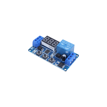
Gate operator control board fuse
A gate operator control board fuse is a critical safety component found on the circuit board of an automatic gate system. Its primary function is to protect the electrical components of the gate operator from damage caused by excessive current, such as a short circuit or an overload.
Essentially, it acts as a sacrificial link in the electrical circuit. If the current flowing through the circuit exceeds a predetermined safe limit, the thin metal wire or strip inside the fuse melts and breaks the circuit. This prevents the surge of electricity from reaching and damaging more expensive and vital components on the control board or in the motor.
Types and Characteristics
Gate operator control board fuses come in various amperage ratings, typically ranging from 0.2 to 15 amps, depending on the specific gate operator model and its power requirements. Some common characteristics include:
- Slow-Blow/Time-Delay Fuses: Many gate operators use "slow-blow" or "time-delay" fuses. These fuses are designed to tolerate brief, temporary current surges that often occur when motors start up without immediately blowing. They only interrupt the circuit if the overload persists for a longer duration.
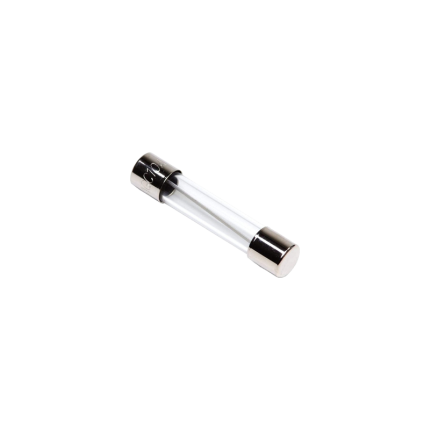
- Physical Form: They can be found in various physical forms, including glass tube fuses (common in older models), blade-style automotive fuses, or sometimes as surface-mount fuses directly on the printed circuit board.
Why Fuses Blow
A blown fuse is usually an indication of an underlying problem, not the problem itself. Common reasons a gate operator fuse might blow include:
- Short Circuit: A direct path for current to flow, bypassing the normal resistance, causing a sudden and large surge.
- Overload: The gate motor or another component drawing more current than it's designed for, perhaps due to mechanical obstruction, a faulty motor, or issues with the gate's movement (e.g., binding hinges, gate dragging on the ground).
- Component Failure: A faulty component on the control board or within the gate operator system itself can cause an abnormal current draw, leading the fuse to blow.
- Power Surges: External power surges from the main electrical supply or lightning strikes can also cause fuses to blow.
Checking and Replacing a Fuse
If your automatic gate stops working, checking the fuse on the control board is often one of the first troubleshooting steps.
- Disconnect Power: Always disconnect all power to the gate operator before attempting any inspection or repair. This includes both AC power and any battery backup systems.
- Locate the Fuse: The fuse is typically located directly on the main control board, often in a small holder or a clear cover. Refer to your gate operator's manual for its exact location.
- Inspect the Fuse:
- For glass tube fuses, you can often visually inspect the wire inside; if it's broken or discolored, the fuse is blown.
- For blade-style fuses, there might be a visible break in the metal strip, or you can use a multimeter set to continuity mode. A blown fuse will show no continuity.
- Replace the Fuse: If the fuse is blown, replace it with a new fuse of the exact same amperage (ampere) and voltage rating. Using a fuse with a higher rating can lead to damage to the control board or other components, as it won't blow when it should. Using a lower rating may cause the fuse to blow unnecessarily.
If the new fuse blows immediately or shortly after replacement, it indicates an ongoing electrical problem that needs to be diagnosed and repaired by a qualified technician. Replacing fuses repeatedly without addressing the root cause can lead to more serious damage to your gate operator system.


Reviews
There are no reviews yet.