Sliding gate
Sliding gate operator gear rack -SLGR2
Ship or pick up from our office.
Sliding gate operator gear rack -SLGR2
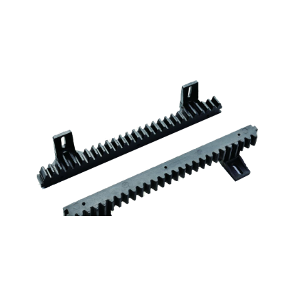
The Sliding Gate Operator Gear Rack SLGR2 is a specific type of toothed bar used in conjunction with a sliding gate operator (motor) to convert its rotational power into the linear motion needed to open and close a sliding gate. Let's break down what SLGR2 likely refers to and its characteristics: Function of a Gear Rack:- Linear Motion: The Sliding Gate Operator Gear Rack SLGR2 is essentially a straight "rack" of teeth that meshes with a small circular gear called a pinion, which is attached to the shaft of the sliding gate operator's motor.
- Power Transmission: As the pinion spins, its teeth engage with the teeth of the gear rack, pushing or pulling the gate horizontally along its track. This is how the motor physically moves the gate.
- Length: The Sliding Gate Operator Gear Rack SLGR2 is specified as being 340 mm (millimetres) in length. This is a relatively short segment. Sliding gates often require multiple sections of gear rack to be joined together to span the entire length of the gate, as most gates are much longer than 340mm.
- Mounting Holes: It has "2 Holes". These holes are pre-drilled for easy attachment to the bottom frame of the sliding gate using screws or bolts.
- Material: While the exact material for this specific SLGR2 is not explicitly stated in all listings, gear racks are commonly made from:
- Steel (most common): Offers high strength, durability, and resistance to wear, making it suitable for heavy gates and high-traffic applications. Often galvanized or treated for corrosion resistance.
- Nylon with a Steel Core: A popular alternative. The nylon exterior provides quieter operation and good corrosion resistance, while the internal steel core offers the necessary strength and stability for the gate's weight and movement. This is a good balance of properties.
- Less commonly, other plastics or stainless steel are used for specific applications.
- "Module": While not explicitly stated for SLGR2, gear racks (and their mating pinions) adhere to a "module" standard (e.g., Module 2, Module 4). The module defines the size of the teeth and the spacing between them, ensuring that the gear rack properly meshes with the pinion gear of the specific sliding gate operator it's intended for. The SLGR2 would have a specific module that matches the operators sold by Royal Gate.
Sliding gate operator limit sensor – Magnetic mechanism
Ship or pick up from our office.
Sliding gate operator limit sensor - Magnetic mechanism
A sliding gate operator limit sensor, often a limit switch, is a crucial component that signals the gate operator when the gate has reached its fully open or fully closed position, stopping the motor and preventing over-travel. These sensors ensure the gate stops at the correct positions, preventing damage to the gate and surrounding structure.
Here's a more detailed explanation:
-
Function:Limit sensors, like limit switches, detect when the gate reaches its extreme open or closed positions.
-
How it works:When the gate reaches the limit, the sensor sends a signal to the gate operator's control board, which then stops the motor.
-
Importance:Without limit sensors, the gate might continue to move, potentially hitting the end posts or other obstructions, causing damage.
-
Types:Common types include magnetic limit switches and photoelectric sensors (photo eyes).
-
Magnetic Limit Switches:These utilize magnets placed on the gate and a magnetic sensor on the operator. When the magnet aligns with the sensor, it triggers the limit switch.
-
Photoelectric Sensors (Photo Eyes):These use infrared beams to detect obstructions. When the beam is broken (e.g., by the gate), the sensor signals the operator to stop.
-
Installation:Proper installation and adjustment of limit sensors are crucial for the reliable operation.
-
Maintenance:Regular inspection and maintenance of limit sensors are recommended, as they can wear out or become misaligned over time.
Sliding gate operator limit sensor -Spring
Ship or pick up from our office.
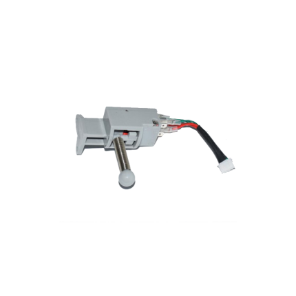
Sliding gate operator limit sensor -Spring
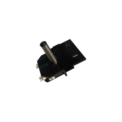
A sliding gate operator limit sensor with a spring mechanism (also known as a mechanical limit switch or spring limit switch) is a common type of sensor used in automatic sliding gate systems to define the gate's fully open and fully closed positions. Here's how it works and what its characteristics are: Purpose of a Limit Sensor: For any automatic gate operator, the system needs to know exactly when the gate has reached its desired open and closed positions. This is crucial for:- Stopping the Motor: Preventing the motor from continuing to run once the gate has reached its limit, which would otherwise cause damage to the gate, the motor, or the track.
- Safety: Ensuring the gate stops precisely where it should, preventing it from hitting obstacles or over-extending.
- Proper Operation: Allowing for features like auto-closing, pedestrian mode, and proper synchronization if it's a dual-gate system.
- Components: A spring limit switch typically consists of:
- A microswitch (an electrical switch that requires very little force to operate).
- A spring-loaded lever, arm, or plunger connected to the microswitch.
- A mounting bracket to attach it to the gate operator or gate frame.
- Mounting: The spring limit switch is usually positioned on the gate operator itself, or on a bracket near the motor.
- Interaction with the Gate:
- On the sliding gate itself, usually along the gear rack or a specific part of the gate frame, two small "stop" tabs or flags are installed – one for the open limit and one for the close limit.
- As the gate moves towards its fully open or fully closed position, one of these tabs/flags will physically contact and push against the spring-loaded lever/plunger of the limit switch.
- This physical contact compresses the spring and activates the microswitch.
- Signal to Control Board: When the microswitch is activated, it sends an electrical signal to the gate operator's main control board.
- Motor Stop: Upon receiving this signal, the control board immediately cuts power to the motor, stopping the gate precisely at that determined limit.
- Physical Contact: The defining feature is that it relies on direct physical contact and force to activate the switch.
- Reliability: Generally reliable as they are a simple mechanical system.
- Durability: Made to withstand repeated physical contact. However, over time, the spring can wear out, lose tension, or the switch itself can be damaged by repeated impacts or debris.
- Adjustability: The position of the "stop" tabs on the gate can be adjusted to fine-tune the exact open and closed positions of the gate.
- Maintenance: May require periodic checks to ensure the spring is intact, the switch is clean, and the "stop" tabs are securely in place and correctly positioned. They can be susceptible to damage from impacts (e.g., if a child's toy or a pet gets in the way of the stop tab).
- Compared to Magnetic Limit Switches:
- Magnetic Limit Switches: These are more common in newer and higher-end gate operators (like many BFT Deimos "Ultra" models). They use magnets attached to the gate and magnetic sensors (reed switches or Hall effect sensors) on the operator. They offer a "contactless" operation, which generally leads to less wear and tear, greater precision, and less susceptibility to environmental debris or physical impact damage.
- Spring/Mechanical Limit Switches: Are typically more cost-effective and simpler in design. They are still widely used, especially in more budget-friendly or older gate operator models.
Sliding gate operator main control board – VDS
Ship or pick up from our office.
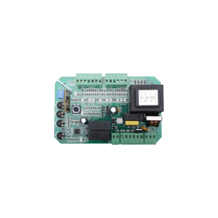
Sliding gate operator main control board – VDS
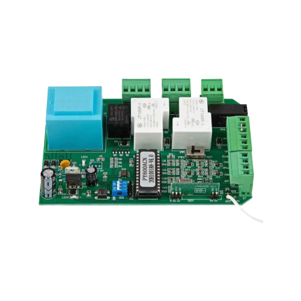
The VDS SIMPLY sliding gate operator's main control board is the central unit that controls the operation of a sliding gate, typically one that weighs up to 600kg.
It's made by VDS Automation, an Italian company known for its gate automation products.
This control board manages functions like opening and closing the gate, potentially adjusting speed and force, and integrating with accessories such as keypads and safety sensors.

-
Central Control:The control board acts as the brain of the gate, receiving signals from remote controls or other input devices and translating them into actions for the gate's motor and other components.
-
Remote Control Integration:It typically includes a built-in radio receiver that can be programmed to work with VDS remote controls.
-
Safety Features:The control board can manage safety mechanisms like anti-squashing systems and potentially adjustable speed and force settings.
-
Easy Installation and Programming:The VDS SIMPLY control board is designed for easy installation, often featuring pre-wired components and straightforward programming.
-
Optional Accessories:It can be integrated with optional accessories like keypads, safety sensors, and other components to enhance functionality.
-
Durability:The control unit is often housed in a box with an air-stop seal to protect it from moisture and insects, and the mechanical parts may be lubricated with lithium grease for longevity.
-
Italian Manufacturing:VDS (Simply SL110) is specifically mentioned as an Italian-made control board, emphasizing quality and reliability.
Sliding gate operator main control board – Zero
Ship or pick up from our office.
Sliding gate operator main control board – Zero
The sliding gate operator main control board (also referred to as a PCB or circuit board) is the central component that manages all the functions of an automatic sliding gate system.
It acts as the "brain" of the gate, receiving signals from various input devices (like remote controls, keypads, or safety sensors) and translating them into actions for the gate's motor and other components.
Here's a more detailed breakdown:
1. Central Control: The control board is the central hub for all gate operations. It receives signals from different sources, such as:
- Remote controls: For opening and closing the gate.
- Keypads: For authorized access.
- Safety sensors: To detect obstructions and prevent accidents.
- Other accessories: Such as loop detectors, intercom systems, etc.
2. Signal Processing: The control board interprets the signals it receives and determines the appropriate action for the gate.
3. Motor Activation: Based on the processed signal, the control board sends instructions to the gate's motor to either open or close the gate.
4. Adjustable Settings: The control board often allows for adjustments to various parameters, including:
- Gate speed: The speed at which the gate opens and closes.
- Opening and closing timers: To control the duration of the gate's movement.
- Safety features: Including force adjustments, obstacle detection sensitivity, and slow-down settings.
Sliding gate operators limit sensor -Spring
Ship or pick up from our office.
Sliding gate operator limit sensor -Spring
A sliding gate operator limit sensor with a spring mechanism (also known as a mechanical limit switch or spring limit switch) is a common type of sensor used in automatic sliding gate systems to define the gate's fully open and fully closed positions. Here's how it works and what its characteristics are: Purpose of a Limit Sensor: For any automatic gate operator, the system needs to know exactly when the gate has reached its desired open and closed positions. This is crucial for:- Stopping the Motor: Preventing the motor from continuing to run once the gate has reached its limit, which would otherwise cause damage to the gate, the motor, or the track.
- Safety: Ensuring the gate stops precisely where it should, preventing it from hitting obstacles or over-extending.
- Proper Operation: Allowing for features like auto-closing, pedestrian mode, and proper synchronization if it's a dual-gate system.
- Components: A spring limit switch typically consists of:
- A microswitch (an electrical switch that requires very little force to operate).
- A spring-loaded lever, arm, or plunger connected to the microswitch.
- A mounting bracket to attach it to the gate operator or gate frame.
- Mounting: The spring limit switch is usually positioned on the gate operator itself, or on a bracket near the motor.
- Interaction with the Gate:
- On the sliding gate itself, usually along the gear rack or a specific part of the gate frame, two small "stop" tabs or flags are installed – one for the open limit and one for the close limit.
- As the gate moves towards its fully open or fully closed position, one of these tabs/flags will physically contact and push against the spring-loaded lever/plunger of the limit switch.
- This physical contact compresses the spring and activates the microswitch.
- Signal to Control Board: When the microswitch is activated, it sends an electrical signal to the gate operator's main control board.
- Motor Stop: Upon receiving this signal, the control board immediately cuts power to the motor, stopping the gate precisely at that determined limit.
- Physical Contact: The defining feature is that it relies on direct physical contact and force to activate the switch.
- Reliability: Generally reliable as they are a simple mechanical system.
- Durability: Made to withstand repeated physical contact. However, over time, the spring can wear out, lose tension, or the switch itself can be damaged by repeated impacts or debris.
- Adjustability: The position of the "stop" tabs on the gate can be adjusted to fine-tune the exact open and closed positions of the gate.
- Maintenance: May require periodic checks to ensure the spring is intact, the switch is clean, and the "stop" tabs are securely in place and correctly positioned. They can be susceptible to damage from impacts (e.g., if a child's toy or a pet gets in the way of the stop tab).
- Compared to Magnetic Limit Switches:
- Magnetic Limit Switches: These are more common in newer and higher-end gate operators (like many BFT Deimos "Ultra" models). They use magnets attached to the gate and magnetic sensors (reed switches or Hall effect sensors) on the operator. They offer a "contactless" operation, which generally leads to less wear and tear, greater precision, and less susceptibility to environmental debris or physical impact damage.
- Spring/Mechanical Limit Switches: Are typically more cost-effective and simpler in design. They are still widely used, especially in more budget-friendly or older gate operator models.
Sliding gate support roller
Ship or pick up from our office.
Sliding gate support roller
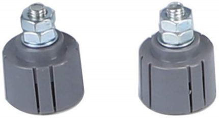
Sliding gate roller guides are essential components of sliding gates that facilitate smooth and controlled movement along a track or rail.
They help the gate stay aligned, preventing it from wobbling or coming off the track during operation. These guides are typically comprised of a bracket (often L-shaped) and one or more rollers, often made of nylon, that minimize friction and ensure quiet, efficient gate movement.
Key functions of sliding gate roller guides:
-
Smooth & Stable Movement:They ensure the gate slides smoothly along the track, preventing jerky movements and noise.
-
Alignment & Stability:They keep the gate aligned with the track, preventing it from wobbling or falling off.
-
Reduced Friction:The rollers minimize friction between the gate and the track, improving the gate's efficiency and lifespan.
-
Enhanced Durability:By reducing friction and stress on the gate and its components, they contribute to the longevity of the entire system.
Types of Sliding Gate Roller Guides:
-
L-Shaped Bracket with Rollers:This is a common type, featuring an L-shaped bracket that can be mounted on a post and nylon rollers that guide the gate.
-
Cantilever Gate Rollers:Specifically designed for cantilever gates (those that don't require a bottom track), these rollers provide support and smooth movement.
-
Adjustable Rollers:Some guides allow for horizontal adjustment of the roller position to accommodate different gate widths.
-
Flat Mount Wheels:Used when there's no need for a wheel cutout, these screw directly onto the bottom rail of the gate.
Materials and Construction:
-
Rollers:Typically made of nylon or other durable materials that can withstand wear and tear.
-
Brackets:Often made of steel (galvanized or stainless steel) for strength and durability.
Applications:
Sliding driveway gates, Security gates, Garden gates, Barn doors, Garage doors, Sheds, and Storage spaces.
In essence, sliding gate roller guides are critical for the proper functioning and longevity of sliding gates, ensuring smooth, reliable, and quiet operation.
Sliding gate V-Groove nylon wheels -SLGWN778MLB
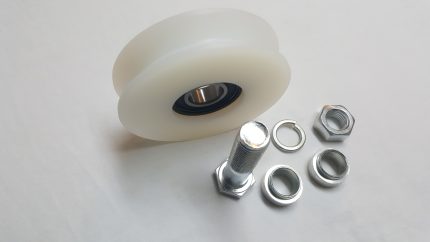
Sliding gate V-Groove nylon wheels -SLGWNS250
Ship or pick up from our office.
*Double bearing *Max 250 Kg *98 mm Diameter (4") x 44 mm Width (1-3/4") (Heavy-duty bolts, nuts, and washers are included)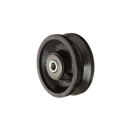
Sliding gate V-Groove wheels -SLGWS800
Ship or pick up from our office.
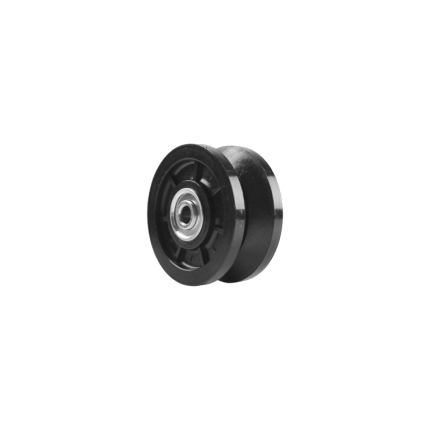
Sliding gate V-Groove wheels -SLGWS800
Sliding gate V-Groove wheels are a fundamental component in a common type of sliding gate system. Unlike cantilever gates that hang above the ground, these gates roll directly on a track installed on the ground. Here's a detailed explanation: What they are: A V-Groove wheel is a type of wheel specifically designed with a V-shaped groove machined into its circumference. This groove perfectly mates with a corresponding V-shaped track, which is usually made of angle iron or a similar steel profile. How they work:- Track Installation: A V-shaped steel track is securely laid and typically anchored into the driveway or ground along the entire length of the gate's travel path. This track acts as the "railroad track" for the gate.
- Wheel Attachment: The V-Groove wheels are attached to the bottom frame of the sliding gate. Depending on the gate's length and weight, multiple wheels will be strategically placed along its underside.
- Guidance and Support: As the gate opens or closes (either manually or with a gate opener), the V-shaped groove of the wheels sits snugly onto the V-shaped track. This tight fit ensures:
- Smooth and Stable Movement: The gate rolls smoothly and without wobbling or derailing.
- Guidance: The wheels effectively guide the gate in a straight line, preventing it from veering off course.
- Load Distribution: The wheels bear the weight of the gate, distributing it evenly along the track.
- Materials: V-Groove wheels are typically made from durable materials to withstand heavy loads and wear:
- Steel (most common): Offers high strength, load capacity, and durability. Often zinc-plated or galvanized for corrosion resistance.
- Cast Iron: More economical but can be more prone to breakage than steel, and may require more frequent lubrication.
- Nylon or High-Impact Polymer: Quieter in operation and excellent for corrosion resistance, but generally have lower load capacities than steel and may not last as long under heavy use.
- Bearings: High-quality V-Groove wheels incorporate sealed bearings (like precision ball bearings). These reduce friction, ensure smooth rolling, and often require no lubrication, making them "maintenance-free."
- Sizes: Available in various diameters (e.g., 3", 4", 6") and load capacities (ranging from hundreds to thousands of pounds per wheel) to suit different gate sizes and weights.
- With or Without Brackets: Some wheels come with integrated mounting brackets for easier installation, while others are just the wheel itself, requiring a custom bracket or housing.
- Stability and Alignment: The V-groove design provides excellent stability, keeping the gate perfectly aligned with the track and preventing it from tilting or derailing.
- High Load Capacity: Especially steel V-Groove wheels, they are designed to handle very heavy gates, making them suitable for large residential, commercial, and industrial applications.
- Durability and Longevity: Made from robust materials, they offer a long service life, particularly with sealed bearings.
- Relatively Simple System: The concept is straightforward, and the components are widely available.
- Ground Track Maintenance: The main drawback compared to cantilever gates is that the ground track can accumulate debris (leaves, dirt, snow, ice). This debris must be regularly cleaned to ensure smooth operation and prevent damage to the wheels or opener. In Surrey, BC's climate, this is an important consideration due to rain and potential for snow.
- Driveway Disruption: Installing a ground track requires cutting into or modifying the driveway surface.
- Noise: While smoother than some other wheel types, they can still produce some noise, particularly if the track is not perfectly clean or if the wheels are worn.
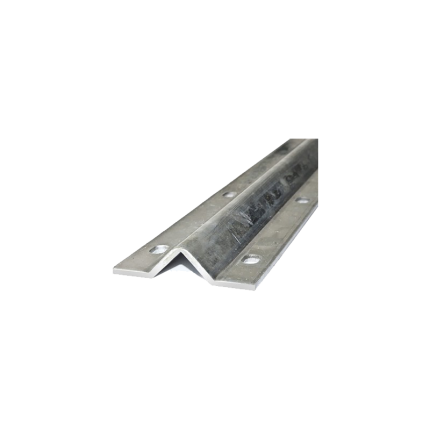
Sliding Gate V-Track
Ship or pick up from our office.
Sliding Gate V-Track
NOTE: For 25 ft sliding gate V-Track, please do not make an online order.Because of the limit of the shipping length and weight, we have to cut the full length of the product (25') to 2 x (12'-6") for pick-up from our store OR 4 x (6'-3") to send by Canada Post.
If your order requires cutting services, additional costs will apply.
To create an order for sliding gate V-Track, please send your request with the shipping address, postal code, and the length of your inquiry in the note. You will receive a quotation with the shipping costs within a maximum of one business day. A sliding gate V-track is a specific type of ground track that a sliding gate rolls on, utilizing wheels with a complementary V-shaped groove. This system is one of the most common ways to implement a sliding driveway gate, especially for residential and light commercial applications. Here's a breakdown: Purpose: The sliding gate V-track as the linear guide and support for the entire sliding gate. It ensures that the gate moves in a straight line, smoothly, and without wobbling or derailing as it opens and closes. It's an integral part of a "rolling gate" system, where the gate literally rolls on the ground. Key Characteristics and Components:- V-Shape Profile: The most defining feature. The track has an inverted V-shape or a 90-degree angle (like an angle iron) with a slightly rounded top. This V-shape mates perfectly with the V-groove wheels attached to the bottom of the gate.
- Materials:
- Galvanized Steel (Most Common): Highly durable, strong, and resistant to corrosion due to the galvanization process. It can handle heavy gates and high traffic volumes. Sections are typically joined together to form the required length.
- Aluminum: Lighter weight and excellent corrosion resistance. Often used for lighter gates or in environments where rust is a major concern (like coastal areas).
- Installation:
- Bolt-Down: The V-track is typically designed to be bolted securely to a concrete driveway or foundation. It has pre-drilled holes for anchor bolts. This allows for easier installation on existing concrete and simpler replacement if a section gets damaged.
- Embeddable (Less Common for DIY): Some V-tracks are designed to be embedded directly into wet concrete during construction.
- Level and Straight: Crucially, the V-track must be installed perfectly level and straight along the entire travel path of the gate to ensure smooth and consistent operation. Any dips, humps, or curves will cause issues with the gate's movement and can put undue strain on the gate operator and wheels.
- Lengths: Sliding gate V-tracks are sold in sections (e.g., 6 feet, 10 feet, 2.4 meters, 3 meters). Multiple sections are joined together using connection pins or by welding to achieve the total required length, which should be at least twice the width of the gate opening to allow the gate to fully retract.
- Complementary Hardware:
- V-Groove Wheels: These are essential and roll directly on top of the V-track. As discussed previously, they have a V-shaped groove that fits snugly into the track.
- Guide Rollers/Posts: Used at the top of the gate to keep it upright and prevent tipping.
- Gate Stops: Installed at the ends of the track to prevent the gate from over-traveling.
- Stability: The sliding gate V-track V-groove design provides excellent lateral stability, keeping the gate aligned and preventing it from wobbling.
- Load Capacity: Due to the direct ground support and robust V-track/wheel combination, these systems can handle very heavy and long gates.
- Simple Mechanical Principle: The system is straightforward, making it reliable.
- Debris Accumulation: The main drawback is that the V-track, being on the ground, is susceptible to collecting dirt, leaves, gravel, snow, and ice. This debris can obstruct the gate's movement, cause wear on the wheels, and may even lead to derailment or damage to the gate opener. Regular cleaning of the track is essential, especially during winter months in Canada.
- Driveway Disruption: Installing a sliding gate V-track requires modifying the driveway surface, often by bolting it down or embedding it in concrete, which creates a slight raised profile.
- Water Drainage: Proper drainage around the track is important to prevent water pooling.
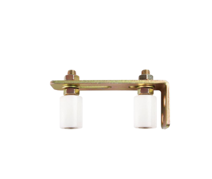
Support Roller
Ship or pick up from our office.
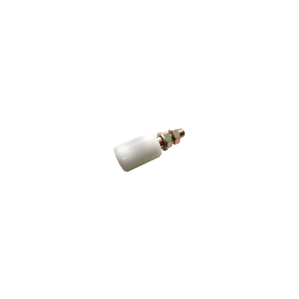
Support Roller
Support Roller for sliding gates are essential components that ensure smooth, stable, and reliable gate operation.
They guide the gate along its track, preventing it from tipping or falling off and ensuring it opens and closes with minimal friction and noise.
Function:
-
Guidance:Support rollers are typically mounted on the gate posts and guide the gate along its track as it opens and closes.
-
Stability:They keep the gate upright and prevent it from swaying or falling out of alignment, especially in windy conditions or with heavier gates.
-
Smooth Operation:By minimizing friction, they allow the gate to slide easily and quietly, enhancing the user experience.
-
Durability:They are designed to withstand the wear and tear of regular use and exposure to the elements.
Types:
- Nylon Rollers: Often used due to their durability, smooth operation, and resistance to corrosion.
- Rubber Rollers: While cheaper, they may leave marks on the gate and wear out faster.
- V-Groove Wheels: Suitable for specific track types and known for their longevity.
Installation:
- Positioning: Support rollers are typically installed on the gate posts, positioned to guide the gate along its track.
- Spacing: A gap of 5-10mm is usually recommended between rollers to allow for some movement and prevent them from doing all the work, especially if the gate is not perfectly balanced.
- Fixation: They are usually secured with bolts or by welding them to the post.
Maintenance:
-
Lubrication:Applying a silicone-based lubricant to the support rollers and other moving parts can help maintain smooth operation and reduce noise.
-
Regular Inspection:Inspecting rollers for wear and tear or damage is recommended to ensure continued reliable performance.


