Accessories
Delay relay 0.5 Sec – AC 24 V to AC 24 V
Ship or pick up from our office.
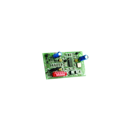
Delay relay 0.5 Sec - AC 24 V to AC 24 V
delay relay 0.5 Sec - AC 24 V to AC 24 V is a type of electrical relay that introduces a 0.5-second time delay in a circuit, specifically designed to operate with a 24-volt AC (Alternating Current) power supply. This means that when the control voltage (24V AC) is applied or removed, the relay's output contacts won't change their state immediately; instead, there will be a half-second pause before they do. Here's a breakdown of what each part of the description means:- Delay Relay (or Time Delay Relay/Timer Relay): This is a control device that, unlike a standard relay, incorporates a timing function. It's used to control an event based on a pre-selected time interval.
- 0.5 Sec: This specifies the duration of the time delay. In this case, it's a very short half-second delay. Time delays can range from milliseconds to hours or even days, depending on the relay.
- AC 24 V (Input/Control Voltage): This indicates the type and voltage of the power supply required to energize the relay's coil or internal control circuitry. "AC" means Alternating Current, and "24 V" is the nominal voltage.
- to AC 24 V (Output/Load Voltage): While not explicitly stated as "output," this implies that the relay is likely intended to switch a 24V AC load. This means the contacts within the relay are rated to handle 24V AC to control another part of the circuit or a device. It's important to note that the load voltage can sometimes be different from the control voltage, but in this specific phrasing, it suggests both are 24V AC.
- On-Delay (Normally-Open, Timed-Closed - NOTC): The most common type. When the control voltage is applied, the timing period begins. After 0.5 seconds, the output contacts close. The contacts remain closed as long as the control voltage is present.
- Off-Delay (Normally-Open, Timed-Open - NOTO): When the control voltage is applied, the output contacts close immediately. When the control voltage is removed, the 0.5-second delay begins. After this delay, the contacts open.
- One-Shot: Provides a single output pulse of a specified duration (in this case, 0.5 seconds) when triggered.
- Repeat Cycle: Alternates between ON and OFF states for defined durations, creating a repeating cycle. This particular relay with a fixed 0.5-second delay is less likely to be a multi-function repeat cycle unless it's just one setting within a programmable unit.
- Sequencing Operations: Ensuring one component starts or stops slightly after another in a controlled sequence.
- Motor Control: Providing a brief delay before starting a motor (e.g., for pre-lubrication pumps to stabilize).
- Safety Interlocks: Implementing a short delay to ensure certain conditions are met before an action can occur.
- HVAC Systems: Timing the activation or deactivation of fans, compressors, or other components.
- Conveyor Systems: Coordinating the starting or stopping of multiple conveyor belts to prevent material jams.
- Lighting Control: For example, a short delay before turning on a light in a specific area
Delay relay 0.5 Sec – AC 24 V to DC 12 V
Ship or pick up from our office.
Delay relay 0.5 Sec - AC 24 V to DC 12 V
A "delay relay 0.5 Sec - AC 24 V to DC 24 V" is a time delay relay that is designed to:- Operate with a control voltage of 24 volts, which can be either Alternating Current (AC) or Direct Current (DC). This dual compatibility (AC/DC 24V) is a key feature, as many relays are specific to one type of current.
- Introduce a delay of 0.5 seconds before its contacts change state. This delay can be an "on-delay" (contacts close/open after 0.5 seconds when power is applied) or an "off-delay" (contacts remain closed/open for 0.5 seconds after power is removed), or other timing functions depending on the specific relay's design.
- Switch or control a separate circuit, which may be a 24V DC circuit. The "AC 24V to DC 24V" in the description refers to the relay's input power compatibility (it can be powered by either 24V AC or 24V DC) and its output capability (it's often used to control 24V DC loads). It is not a direct AC to DC converter for the load it's switching, but rather indicates its flexible control voltage. The relay itself doesn't convert the power; it merely switches it on or off after a delay. If the controlled circuit specifically requires DC, the relay's contacts would simply switch the 24V DC power to that circuit.
- Prevent false triggering: A brief fluctuation in voltage or a momentary signal might cause immediate activation in a standard relay. A short delay (like 0.5 seconds) can prevent such nuisance activations.
- Create timed sequences: In automated processes, certain steps may need to occur in a specific order with set delays in between. For example, a delay relay could ensure one motor starts before another or that a safety purge cycle completes before a furnace ignites.
- Control motor starts/stops: They can be used for "soft starting" motors, gradually increasing voltage to reduce inrush current, or for ensuring a motor has fully stopped before another action begins.
- HVAC systems: They prevent "short cycling" of compressors, which can damage the unit, by introducing a delay between successive starts.
- Lighting control: Ensuring lights stay on for a set period after activation (e.g., in stairwells) or controlling emergency lighting.
- Security systems: Providing a brief delay before an alarm triggers, allowing authorized personnel to disarm the system.
- On-delay (Delay on Make): The most common type. The contacts change state only after the set time delay has elapsed after the control voltage is applied.
- Off-delay (Delay on Break): The contacts change state immediately when the control voltage is applied, but only return to their original state after the set time delay has elapsed after the control voltage is removed.
- Interval: The contacts change state immediately when the control voltage is applied, and then return to their original state after the set time delay.
- Repeat Cycle: The relay continuously cycles between on and off states with specific time delays as long as the control voltage is applied.
Digital programmable ON/OFF relay
Ship or pick up from our office.
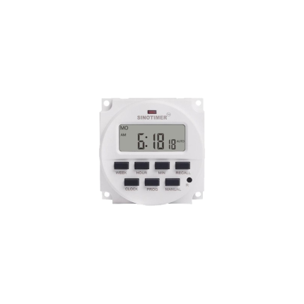
Digital programmable ON/OFF relay
A digital programmable ON/OFF relay is an electronic switch that can be programmed to turn electrical devices on or off at specific times or intervals. It combines the fundamental switching functionality of a traditional relay with the advanced timing and control capabilities of a digital timer or microcontroller. This allows for automated control of various devices and systems without constant human intervention. How it Works At its core, a digital programmable ON/OFF relay operates similarly to a standard relay by using a small electrical current to control a larger electrical circuit. However, the "digital programmable" aspect introduces a sophisticated timing mechanism.- Digital Interface: Unlike mechanical or analog timer relays with physical dials, digital programmable relays feature an LED or LCD display and a keypad or buttons for programming. This allows users to set precise ON/OFF times, durations, and sequences.
- Microcontroller-Based: Most digital programmable relays use a microcontroller to manage the timing and control logic. This internal "brain" keeps track of time and executes the programmed instructions.
- Timing Functions: These relays offer a wide range of timing functions, including:
- On-delay: The relay turns on after a preset delay once activated.
- Off-delay: The relay turns off after a preset delay once deactivated.
- Interval timing: The relay stays on for a specific duration after activation.
- Cyclic operation: The relay repeatedly cycles ON and OFF at set intervals.
- Astronomic timing: Some advanced models can turn devices on/off based on sunrise and sunset times by calculating the solar position.
- Photocell integration: Others may include light sensors to activate based on ambient light levels.
- Memory Retention: Many programmable relays can store settings in memory even after a power interruption, ensuring that the programmed schedule is not lost.
- Programmable Timing: Offers precise control over when devices turn on and off.
- Automation: Reduces the need for manual operation, leading to increased efficiency.
- Energy Savings: Allows for optimization of energy usage by ensuring devices are only active when needed.
- Flexibility and Versatility: Can be configured for a wide array of applications due to various timing modes.
- Compact Design: Often more compact than systems using multiple hardwired timers and relays.
- Ease of Use: User-friendly interfaces for setting up programs.
- Reliability: Many are solid-state, meaning they have no moving parts, which increases durability and reduces noise compared to electromechanical relays.
- Home Automation: Controlling lighting, appliances, or other devices based on a preset schedule (e.g., security lights, garden irrigation).
- Industrial Automation: Managing machinery, conveyors, pumps, motors, and other equipment in factories or manufacturing facilities.
- Building Management Systems: Automated control of HVAC systems (heating, ventilation, air conditioning), lighting (e.g., streetlights turning on at dusk), and security systems.
- Commercial Applications: Used in vending machines, amusement equipment, and commercial appliances.
- Agriculture: Controlling irrigation pumps or greenhouse lighting.
- Security Systems: Activating alarms or security lights at specific times or in response to sensors.
Diode 1N4007
Ship or pick up from our office.
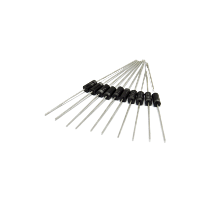
Diode 1N4007
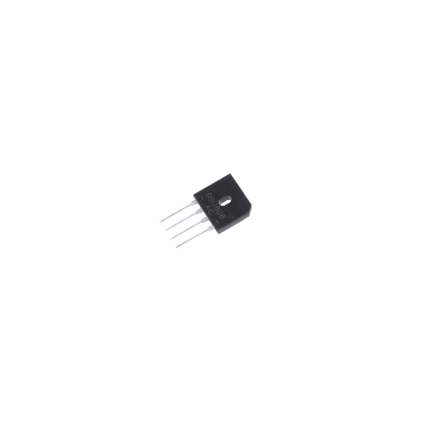
The 1N4007 is a very common and versatile silicon rectifier diode. It's part of the 1N400x series of general-purpose diodes, with the "7" indicating its specific voltage rating. Key Characteristics- Rectifier Diode: Its primary function is to convert alternating current (AC) into pulsating direct current (DC) by allowing current to flow in only one direction.
- High Reverse Voltage Rating: The 1N4007 can withstand a peak repetitive reverse voltage () of 1000V. This makes it suitable for high-voltage applications.
- Average Forward Current: It can handle an average forward current () of 1 Ampere (1A).
- Forward Voltage Drop: When conducting in the forward direction, it has a relatively low forward voltage drop () of approximately 0.7V to 1.1V. This voltage drop represents the power lost within the diode.
- Surge Current Capability: It can handle a non-repetitive peak surge current () of up to 30A for short durations, which is useful for handling initial power-on surges.
- Package Type: It typically comes in a DO-41 axial-lead package, which is a small, cylindrical plastic package with leads on both ends.
- Operating Temperature Range: It operates reliably over a wide temperature range, typically from -55°C to +175°C.
- Forward Bias: When a positive voltage is applied to the anode (P-side) and a negative voltage to the cathode (N-side), the diode is forward-biased. If the applied voltage exceeds the forward voltage drop (around 0.7V for silicon diodes), the diode conducts, allowing current to flow from anode to cathode.
- Reverse Bias: When a negative voltage is applied to the anode and a positive voltage to the cathode, the diode is reverse-biased. In this state, the diode acts like an open switch, blocking current flow. The 1N4007 is designed to withstand up to 1000V in this reverse-biased state before breaking down.
- Rectifier Circuits:
- Half-wave and Full-wave Rectifiers: Essential for converting AC power from the mains (like in household appliances) to DC power for electronic devices.
- Bridge Rectifiers: Used to convert the entire AC waveform into pulsating DC, achieving more efficient rectification.
- Power Supplies: Used for rectifying the AC input in power supply units to provide DC voltage to various components.
- Voltage Protection:
- Reverse Polarity Protection: Prevents damage to circuits if the power supply is connected with incorrect polarity.
- Freewheeling Diodes (Flyback Diodes): Protect sensitive components from voltage spikes generated by inductive loads (like relays, motors, and solenoids) when their magnetic field collapses.
- Voltage Spike Suppression: Helps to suppress transient voltage spikes that can occur due to switching events or lightning, safeguarding delicate electronics.
- Inverters and Converters: Used in various power conversion circuits.
- Current Flow Regulation: Can be used in simple current limiting or flow control applications.
Diode 1N5408
Ship or pick up from our office.
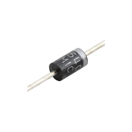
Diode 1N5408
The 1N5408 is a common general-purpose rectifier diode. It's designed to allow electric current to flow primarily in one direction, making it crucial for converting alternating current (AC) to direct current (DC). Think of it like a one-way valve for electricity. It belongs to the 1N540x series of power diodes, known for their ability to handle relatively high current and voltage. Here are its key characteristics and common uses: Key Features- High Reverse Voltage Rating: It can withstand a maximum repetitive reverse voltage () of 1000V. This means it can block high voltages when current tries to flow in the "wrong" direction.
- High Forward Current Capacity: It's rated for an average rectified forward current () of 3 Amperes (A). This indicates it can handle a significant amount of current flowing through it in the correct direction.
- High Surge Current Capability: The 1N5408 can handle non-repetitive peak forward surge currents () of up to 200A for short durations, protecting circuits from sudden power spikes.
- Low Forward Voltage Drop: When conducting, it has a relatively low forward voltage drop () of approximately 1.0V to 1.2V at its rated current. A lower voltage drop means less power is lost as heat.
- Standard Recovery: It's a "standard recovery" diode, meaning its switching speed is relatively slow compared to fast recovery diodes. This makes it suitable for power rectification at lower frequencies (like 50/60 Hz AC).
- DO-201 Package: It typically comes in a DO-201 axial-leaded package, which is a through-hole component with leads extending from both ends, allowing for easy mounting on circuit boards.
- Wide Operating Temperature Range: It can operate and be stored in a wide temperature range, typically from -65°C to +175°C.
- Power Supplies and Rectifiers: This is its primary application. It efficiently converts AC input voltage into pulsating DC, which can then be smoothed by capacitors to provide a stable DC output for electronic devices. This includes full-wave and half-wave rectifier circuits.
- Battery Chargers: Used to convert AC wall power into DC for charging batteries.
- Voltage Regulation Circuits: Helps in maintaining a stable output voltage by rectifying current.
- Protection Circuits: Its ability to block reverse current makes it useful for reverse polarity protection, preventing damage to sensitive components if the power supply is connected incorrectly.
- Freewheeling Diode: Used in inductive circuits (like those with relays or motors) to provide a path for stored energy to dissipate when the current is switched off, preventing voltage spikes that could damage other components.
- Voltage Doubler Circuits: Can be used in circuits designed to effectively double the input voltage.
Diode Bridge GBU808
Ship or pick up from our office.
Diode Bridge GBU808
*8A *800V *Single Phase *Rectifier IC Chip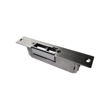
Door Strike Lock
Ship or pick up from our office.
Door Strike Lock
*Fail-Secure/Fail-Safe *Capacity: 100 Kg *DC 12 VAn electric strike is an electromechanical lock release device that replaces a standard door strike plate.
It allows a door to be opened remotely, typically via an access control system, without manually retracting the latch. When activated, the electric strike releases the latch, enabling the door to be opened.
Here's a more detailed explanation:
Functionality:
-
Replaces Standard Strike:Electric strikes are installed in the door frame, taking the place of the standard strike plate.
-
Remote Release:They are designed to work with various access control systems, such as keypads, card readers, or intercoms.
-
Activation:When an authorized signal is received (e.g., a code is entered, a card is swiped), the electric strike releases the latch, allowing the door to be opened.
-
Fail-Safe or Fail-Secure:Electric strikes can be configured in either a fail-safe or fail-secure mode.
- Fail-safe: In this mode, the door unlocks when power is lost, making it suitable for safety applications where access is needed during power outages.
- Fail-secure: In this mode, the door remains locked when power is lost, requiring power to unlock, making it suitable for high-security applications.
How it Works:
- The electric strike contains a solenoid, which is an electromagnet.
- When the solenoid is activated by an electrical signal, it moves a component (like an armature) that allows the latch to move freely.
- This movement releases the door, allowing it to be opened.
Key Differences from Other Locks:
-
Electric vs. Magnetic Locks:Unlike magnetic locks, which use powerful magnets to hold the door closed, electric strikes release the latch mechanism.
-
Remote Access:Electric strikes offer remote access control, allowing doors to be unlocked without manual intervention.
-
Versatility:They can be used with various locking mechanisms, including cylindrical, mortise, and rim exit devices.
Common Applications:
-
Access Control:Electric strikes are a core component of access control systems in commercial and residential settings.
-
Security:They provide a higher level of security compared to standard locks, especially when used with fail-secure configurations.
-
Safety:In fail-safe configurations, they ensure safe egress during emergencies.
-
Specific Areas:They are commonly found in reception areas, daycare centers, and other locations where controlled access is needed.
Electric Rim Lock RGEL1093
Ship or pick up from our office.
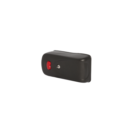
Electric Rim Lock RGEL1093
*Capacity: 2000 Kg *DC 12 V *15 W (5 x release keys are included) This is a heavy-duty electric lock that holds the gate closed. The lock latches strongly to the hook and prevents the gate to be opened by wind or intruders. It will release automatically before the arms start moving. There are five keys in the package for unlocking during power outages. Free installation session is provided in our office. Watch previous project videos on our YouTube channel.- Heavy Duty
- High Security
- Quiet Operation
- Compatible with single and double swing gates
- Keeps full privacy gates in place in windy weather
The RGEL1093 is a heavy-duty electric rim lock designed for gates. It latches securely to prevent opening by wind or intruders and releases automatically before gate movement. The lock includes five keys for manual unlocking during power outages.
Here's a more detailed breakdown:
-
Function:The RGEL1093 is a surface-mounted lock that provides a secure latch for gates.
-
Security:It is designed to withstand strong winds and prevent unauthorized entry.
-
Automatic Release:The lock releases automatically as the gate's opening mechanism starts to move.
-
Power Outages:The inclusion of five keys allows for manual operation when power is unavailable.
-
Installation:It's a rim lock, meaning it's mounted on the surface of the gate, rather than being mortise-set into the edge.
-
Typical Use:Electric rim locks are often used in conjunction with access control systems (like intercoms or keypads) for residential and commercial applications.
Exit Button RCTPB801
Ship or pick up from our office.
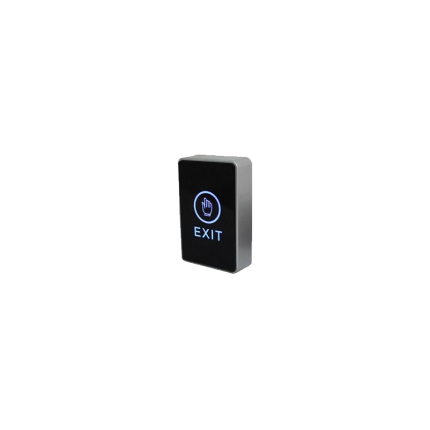
Exit Button RCTPB801
*Touch *Backlight *DC 12V *COM-NC-NOAn Exit push button, also known as a push-to-exit button, is a device used in access control systems to allow individuals to exit a secured area without needing to use their access credentials.
It's a simple, user-friendly button that, when pressed, temporarily unlocks or releases the door, enabling quick and easy egress. These buttons are commonly found near exit doors in buildings, especially those with magnetic locks or other electronic locking mechanisms.
Here's a more detailed explanation:
-
Function:An exit push button is wired to the access control system and, when pressed, sends a signal to release the door's locking mechanism, allowing a person to exit.
-
Purpose:They provide a convenient and safe way to exit a secured area, especially in emergencies or when other access methods (like card readers) might not be available.
-
Types:Exit push buttons can be traditional mechanical buttons or touchless sensors that activate when a hand is waved in front of them.
-
Importance:These buttons are crucial for meeting fire and building codes, as well as ensuring accessibility for all individuals.
-
Applications:Exit push buttons are used in various settings, including commercial buildings, residential complexes, and industrial facilities.

Exit Button SQTPB801
Ship or pick up from our office.
Exit Button SQTPB801
*Touch *Backlight *DC 12V *COM-NC-NOAn Exit push button, also known as a push-to-exit button, is a device used in access control systems to allow individuals to exit a secured area without needing to use their access credentials.
It's a simple, user-friendly button that, when pressed, temporarily unlocks or releases the door, enabling quick and easy egress. These buttons are commonly found near exit doors in buildings, especially those with magnetic locks or other electronic locking mechanisms.
Here's a more detailed explanation:
-
Function:An exit push button is wired to the access control system and, when pressed, sends a signal to release the door's locking mechanism, allowing a person to exit.
-
Purpose:They provide a convenient and safe way to exit a secured area, especially in emergencies or when other access methods (like card readers) might not be available.
-
Types:Exit push buttons can be traditional mechanical buttons or touchless sensors that activate when a hand is waved in front of them.
-
Importance:These buttons are crucial for meeting fire and building codes, as well as ensuring accessibility for all individuals.
-
Applications:Exit push buttons are used in various settings, including commercial buildings, residential complexes, and industrial facilities.
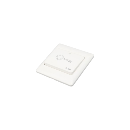
Exit push button ALKPB2015
Ship or pick up from our office.
Exit push button ALKPB2015
The ALKPB2015 is a wired exit push button commonly used in access control systems for doors and gates. Here's a breakdown of what it is and how it functions:- Purpose: Its primary function is to trigger the release of an electric door lock or gate operator, allowing for a quick and controlled exit from a secured area. It's often referred to as a "request to exit" (REX) device.
- Wired Connection: As the name suggests, it's physically connected to the building's electrical system and the door's locking mechanism.
- Momentary Activation: When pressed, the button momentarily completes an electrical circuit, sending a signal to the lock release.
- Door Release: This signal typically causes an electric strike or magnetic lock to disengage, allowing the door to be opened.
- Automatic Relock: Once the button is released, the lock re-engages, securing the door again.
- Common Applications:
- Access Control Systems: Used in conjunction with card readers, keypads, or other entry systems to provide a convenient exit method.
- ADA Compliance: Often designed with features like large, accessible buttons for ease of use by individuals with disabilities.
- Emergency Egress: Crucial for fire safety and other emergencies, providing a reliable way to quickly exit a secured space.
- Security: While providing an exit, it doesn't compromise overall security for entry, as a separate access control system is typically required for entry.
- Features (typical for this type of button):
- Wired connection
- Momentary switch
- NO/NC/COM contacts (Normally Open/Normally Closed/Common) for versatile wiring with different lock types.
- Designed for indoor use (though some exit buttons may have weather-resistant options).
- Often made with durable materials like stainless steel.
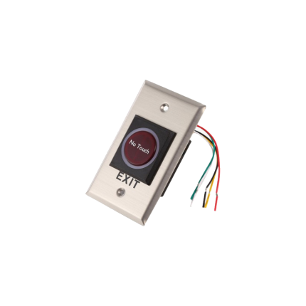
Exit push button RCTPB602
Ship or pick up from our office.
Exit push button RCTPB602
*No Touch *Backlight *DC 12V *COM-NC-NO The RCTPB602 is a wired exit push button commonly used in access control systems. Its primary function is to allow individuals to exit a secured area. Here's a breakdown of its key aspects: Functionality 🚪 The RCTPB602 is a request-to-exit (REX) device. When activated, it sends a signal to an access control panel or directly to a door's electric lock (like an electric strike or magnetic lock), causing the door to unlock and allow egress. This type of button is often used for:- Controlled exit: Ensuring that people can freely exit a secured area without needing a key or credential, while maintaining security on the entry side.
- Emergency egress: Providing a simple and quick way to open a door in an emergency situation.
- Wired Connection: It's designed to be hardwired into an access control system.
- Momentary Operation: It usually functions as a momentary switch, meaning the circuit is activated only while the button is pressed, and returns to its original state when released.
- Output Contacts: It typically provides normally open (NO) and normally closed (NC) contacts, along with a common (COM) contact, allowing it to be integrated with various locking mechanisms.
- Working Voltage: It generally operates on 12VDC, which is common for access control devices.
- Material: Often made with durable materials like an abrasion-resistant panel and a plastic button.
- Application: Suitable for use with various gate frames and doors in access control setups.


