Shop

Solar charge controller
Ship or pick up from our office.
Solar charge controller
A solar charge controller is an electronic device that regulates the flow of electricity from solar panels to a battery bank, protecting the batteries from overcharging and over-discharging. It's a crucial component in off-grid and hybrid solar power systems. Key Functions of a Solar Charge Controller- Preventing Overcharging: Solar panels can produce varying amounts of electricity depending on sunlight intensity. If this unregulated power is sent directly to batteries, it can lead to overcharging, which damages the batteries, reduces their lifespan, and can even pose a safety risk (e.g., overheating, gassing). The charge controller monitors the battery's voltage and reduces or stops the current flow when the battery reaches its full charge.
- Preventing Over-discharging: Some charge controllers also have a low voltage disconnect (LVD) feature that protects the battery from being excessively drained. Deep discharging can also cause irreversible damage to batteries. The controller will disconnect the load when the battery voltage drops below a certain threshold.
- Optimizing Charging: Modern charge controllers use advanced technologies to ensure the batteries are charged efficiently, maximizing the energy harvested from the solar panels.
- Reverse Current Prevention: At night, when solar panels aren't producing power, there's a risk of electricity flowing back from the batteries to the panels, which would drain the batteries. Charge controllers include a diode or similar mechanism to prevent this reverse current flow.
- System Protection: Many controllers offer additional safeguards against issues like short circuits, overloads, and reverse polarity.
- How they work: PWM controllers regulate the voltage by rapidly switching the solar panel input on and off. The "width" of these pulses is adjusted to control the average voltage and current sent to the battery. When the battery is nearly full, the pulses become shorter, reducing the charging current.
- Advantages: They are generally less expensive and simpler in design, making them suitable for smaller, less complex solar systems (e.g., small RV setups, solar lighting).
- Disadvantages: They are less efficient than MPPT controllers, especially in conditions where the solar panel's voltage significantly differs from the battery voltage. They essentially "pull down" the solar panel's voltage to match the battery, leading to energy loss.
- How they work: MPPT controllers are more sophisticated. They can "track" the maximum power point (MPP) of the solar panel. The MPP is the optimal combination of voltage and current at which the solar panel produces the most power. The MPPT controller converts any excess voltage from the solar panels into additional current, thereby maximizing the energy sent to the battery. It's like an automatic transmission that adjusts the gear to get the most power from the engine.
- Advantages: They are significantly more efficient than PWM controllers (often 10-30% more, especially in colder temperatures or when the battery is deeply discharged). They are ideal for larger, more complex solar systems and those where the solar panel array voltage is higher than the battery bank voltage. This also allows for longer wiring runs with less power loss.
- Disadvantages: MPPT controllers are more expensive due to their advanced technology.
Radio receiver RGRR2C
Ship or pick up from our office.
Radio receiver RGRR2C
*AC/DC 12-24 V *2-CH *433 MHz *Rolling code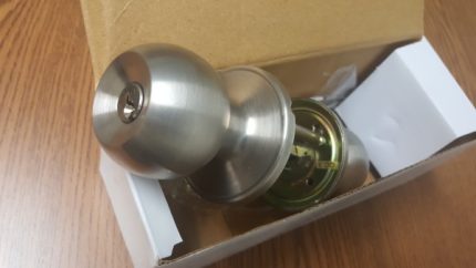
Pedestrian gate manual lock (One side key)
Ship or pick up from our office.
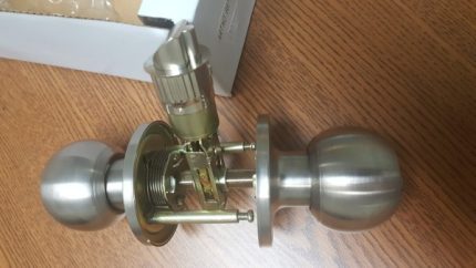
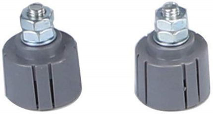
Pedestrian gate manual lock (One side key)
A "pedestrian gate manual lock (one side key)" refers to a type of locking mechanism for a gate that is operated manually and requires a key to unlock it from one side, while the other side allows for easy exit without a key. Here's a breakdown of its key features:- Manual Operation: This lock doesn't rely on electricity or automation. You physically use your hand to engage or disengage the locking mechanism.
- One-Sided Key Access: The defining characteristic is that a physical key is needed to unlock the gate from one specific side (usually the exterior or entry side).
- Easy Exit (Thumb-Turn, Latch, or Push Pad): On the interior or exit side, there's typically a simple mechanism like a thumb-turn, lever, push pad, or a basic latch that allows for quick and easy opening without needing a key. This is often a safety feature, especially for emergency exits.
- Security: It provides a basic level of security, preventing unauthorized entry from the keyed side.
- Power Independence: Since it's manual, it's not affected by power outages.
- Common Use Cases: These locks are frequently found on garden gates, backyard gates, pool gates, and other pedestrian access points where controlled entry is desired but a quick exit is also necessary.
Radio receiver R5130
Ship or pick up from our office.
Radio receiver R5130
(Compatible with the wireless keypad control KW125) *AC/DC 12-24 V *2 Channels *433.92 MHz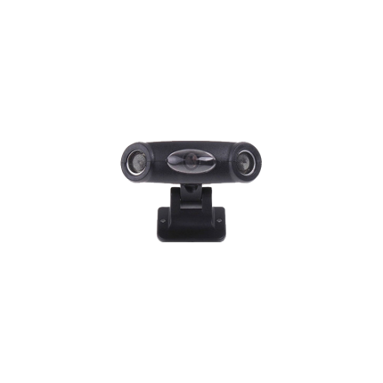
Vehicle alarm ultrasonic sensor
Ship or pick up from our office.
Vehicle alarm ultrasonic sensor
A vehicle alarm ultrasonic sensor is a type of motion sensor used in car alarm systems to detect movement within the interior of a vehicle when the alarm is armed. It's designed to provide an extra layer of security by catching intruders who might try to gain access by breaking a window or otherwise entering the cabin without opening a door. Here's how it generally works:- Emission of Ultrasonic Waves: When the car alarm system is armed, the ultrasonic sensor (or typically a pair of sensors, one on each side of the front of the vehicle, often mounted on the A-pillars) emits high-frequency sound waves. These sound waves are beyond the range of human hearing, hence "ultrasonic." These waves fill the interior space of the vehicle.
- Monitoring for Echoes: The sensor continuously monitors the echoes of these sound waves as they bounce off the surfaces within the car's cabin (seats, dashboard, windows, roof, etc.). This creates a consistent pattern of reflected waves.
- Detection of Disturbance: If an intruder enters the vehicle, or if there's any significant movement within the cabin (e.g., someone reaches in through a broken window, or a pet is left inside and moves around), this movement disrupts the established pattern of the ultrasonic waves. The sound waves bounce back differently, indicating a change in the air pressure or the environment within the car.
- Alarm Trigger: When the sensor detects this disturbance or change in the reflected wave pattern, it signals the car's alarm system. The alarm then triggers, typically sounding the horn, flashing the lights, and in some cases, activating a dedicated siren.
- Interior Protection: Its primary purpose is to detect intrusion into the passenger compartment, complementing other sensors like door, hood, and trunk sensors.
- Invisible Barrier: It creates an "invisible" protective barrier within the vehicle's cabin.
- Sensitivity: Ultrasonic sensors are quite sensitive and can detect even minor movements, which makes them effective against various forms of unauthorized entry.
- False Alarm Reduction: Quality ultrasonic sensors are designed to minimize false alarms. However, factors like leaving windows open, a sunroof ajar, or having pets or large insects inside the car can sometimes trigger them.
- Compatibility: They are often integrated into factory-installed alarm systems in newer vehicles, but can also be added as aftermarket components to enhance existing security systems.
- Adjustable Sensitivity: Many systems allow for adjustment of the sensor's sensitivity to tailor its performance to different environments or situations.
- Not for Convertibles: Due to their reliance on enclosed air space and reflected sound waves, ultrasonic sensors are generally not suitable for convertibles or vehicles with soft tops, as the open or flexible roof would not properly reflect the sound waves, leading to false alarms or ineffective monitoring.
Sliding gate operator limit sensor – Magnetic mechanism
Ship or pick up from our office.
Sliding gate operator limit sensor - Magnetic mechanism
A sliding gate operator limit sensor, often a limit switch, is a crucial component that signals the gate operator when the gate has reached its fully open or fully closed position, stopping the motor and preventing over-travel. These sensors ensure the gate stops at the correct positions, preventing damage to the gate and surrounding structure.
Here's a more detailed explanation:
-
Function:Limit sensors, like limit switches, detect when the gate reaches its extreme open or closed positions.
-
How it works:When the gate reaches the limit, the sensor sends a signal to the gate operator's control board, which then stops the motor.
-
Importance:Without limit sensors, the gate might continue to move, potentially hitting the end posts or other obstructions, causing damage.
-
Types:Common types include magnetic limit switches and photoelectric sensors (photo eyes).
-
Magnetic Limit Switches:These utilize magnets placed on the gate and a magnetic sensor on the operator. When the magnet aligns with the sensor, it triggers the limit switch.
-
Photoelectric Sensors (Photo Eyes):These use infrared beams to detect obstructions. When the beam is broken (e.g., by the gate), the sensor signals the operator to stop.
-
Installation:Proper installation and adjustment of limit sensors are crucial for the reliable operation.
-
Maintenance:Regular inspection and maintenance of limit sensors are recommended, as they can wear out or become misaligned over time.
Remote Control Radio Receiver
Ship or pick up from our office.
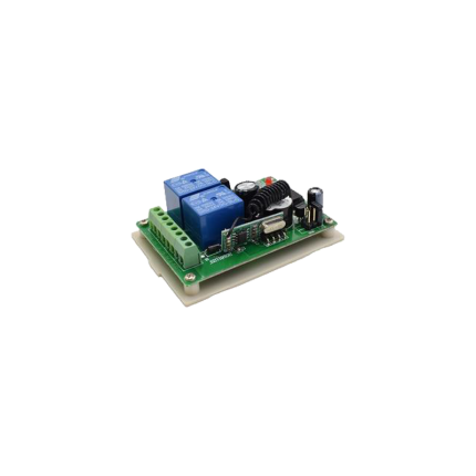
Remote Control Radio Receiver
- NC/NO Output
- Easy to program new remotes
- The remote control button is covered to prevent accidental pressing.
- This radio receiver can be added to almost all the gate operators such as Italian, Chinese, swing gate operators, sliding gate operators, and overhead garage doors.
- Compatible with 100 remotes.
- Small case and easy to install
- The wireless RF signals can pass through walls, floors, doors, or windows. You can use two or more units in the same place.
A gate opener's remote control radio receiver is a device that receives radio signals from a handheld remote control, triggering the gate opener's motor to open or close the gate.
Here's a more detailed explanation:
-
Receives Signals:The receiver picks up radio waves transmitted by the remote control.
-
Decodes Commands:It interprets the specific signal pattern to understand the desired action (e.g., open, close, stop).
-
Controls Devices:The receiver then sends signals to the gate opener's motor, causing it to move the gate accordingly.
-
Part of a System:It's a crucial component of the remote control system, working with the transmitter (remote) to enable wireless control of the gate.
-
Frequency:Gate opener receivers typically operate on frequencies like 433 MHz or 315 MHz.
-
Installation:The receiver is usually wired to the gate operator's control board and may require programming to associate it with specific remote controls.
Sliding gate V-Groove wheels -SLGWS800
Ship or pick up from our office.
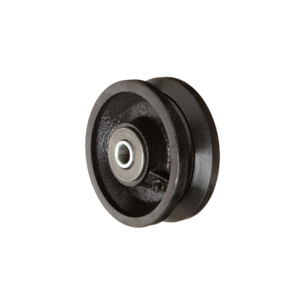
Sliding gate V-Groove wheels -SLGWS800
Sliding gate V-Groove wheels are a fundamental component in a common type of sliding gate system. Unlike cantilever gates that hang above the ground, these gates roll directly on a track installed on the ground. Here's a detailed explanation: What they are: A V-Groove wheel is a type of wheel specifically designed with a V-shaped groove machined into its circumference. This groove perfectly mates with a corresponding V-shaped track, which is usually made of angle iron or a similar steel profile. How they work:- Track Installation: A V-shaped steel track is securely laid and typically anchored into the driveway or ground along the entire length of the gate's travel path. This track acts as the "railroad track" for the gate.
- Wheel Attachment: The V-Groove wheels are attached to the bottom frame of the sliding gate. Depending on the gate's length and weight, multiple wheels will be strategically placed along its underside.
- Guidance and Support: As the gate opens or closes (either manually or with a gate opener), the V-shaped groove of the wheels sits snugly onto the V-shaped track. This tight fit ensures:
- Smooth and Stable Movement: The gate rolls smoothly and without wobbling or derailing.
- Guidance: The wheels effectively guide the gate in a straight line, preventing it from veering off course.
- Load Distribution: The wheels bear the weight of the gate, distributing it evenly along the track.
- Materials: V-Groove wheels are typically made from durable materials to withstand heavy loads and wear:
- Steel (most common): Offers high strength, load capacity, and durability. Often zinc-plated or galvanized for corrosion resistance.
- Cast Iron: More economical but can be more prone to breakage than steel, and may require more frequent lubrication.
- Nylon or High-Impact Polymer: Quieter in operation and excellent for corrosion resistance, but generally have lower load capacities than steel and may not last as long under heavy use.
- Bearings: High-quality V-Groove wheels incorporate sealed bearings (like precision ball bearings). These reduce friction, ensure smooth rolling, and often require no lubrication, making them "maintenance-free."
- Sizes: Available in various diameters (e.g., 3", 4", 6") and load capacities (ranging from hundreds to thousands of pounds per wheel) to suit different gate sizes and weights.
- With or Without Brackets: Some wheels come with integrated mounting brackets for easier installation, while others are just the wheel itself, requiring a custom bracket or housing.
- Stability and Alignment: The V-groove design provides excellent stability, keeping the gate perfectly aligned with the track and preventing it from tilting or derailing.
- High Load Capacity: Especially steel V-Groove wheels, they are designed to handle very heavy gates, making them suitable for large residential, commercial, and industrial applications.
- Durability and Longevity: Made from robust materials, they offer a long service life, particularly with sealed bearings.
- Relatively Simple System: The concept is straightforward, and the components are widely available.
- Ground Track Maintenance: The main drawback compared to cantilever gates is that the ground track can accumulate debris (leaves, dirt, snow, ice). This debris must be regularly cleaned to ensure smooth operation and prevent damage to the wheels or opener. In Surrey, BC's climate, this is an important consideration due to rain and potential for snow.
- Driveway Disruption: Installing a ground track requires cutting into or modifying the driveway surface.
- Noise: While smoother than some other wheel types, they can still produce some noise, particularly if the track is not perfectly clean or if the wheels are worn.
Gate drop ground latch
Ship or pick up from our office.
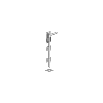
Gate drop ground latch
A gate drop ground latch, also known as a cane bolt or drop rod, is a mechanism used to secure a gate in the open or closed position by inserting a rod into the ground.
It's typically used for double gates to keep one side stationary while the other is latched. It helps prevent gates from moving in the wind and adds extra security.
Here's a more detailed explanation:
How it works:
- A metal rod (the drop rod or cane bolt) is attached to the gate and slides through brackets or guides.
- When the gate is in the desired position (open or closed), the rod is lowered into a hole or receiver in the ground, securing the gate.
- To open the gate, the rod is lifted out of the ground and turned out of the way.
Key features and benefits:
- Secures gates: Prevents gates from swinging open or closed due to wind or other factors.
- Versatile: Can be used on various gate types, including wood, metal, and vinyl.
- Double gate support: Especially useful for securing one side of a double gate while the other is latched.
- Added security: Can be used in conjunction with other latches for increased security.
- Easy installation: Generally involves mounting brackets and drilling a hole for the rod.
- Durable: Made of materials like steel, often with a powder coat finish for weather resistance.
Radio remote control receiver
Ship or pick up from our office.
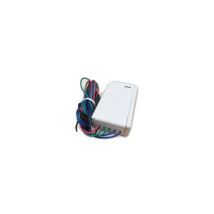
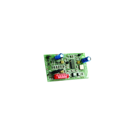
Radio remote control receiver
One remote control is included (Compatible with Home-Link system) *DC 12-24 V *2 Channels *315 MHzA radio remote control receiver is an electronic device that receives signals from a remote control and triggers the gate's motor to open or close.
It acts as the "ear" for the gate opener, interpreting the radio signals sent by the remote. These receivers are crucial for the functionality and convenience of automated gate systems.
Here's a more detailed explanation:
Function:
- The receiver is designed to detect the specific radio frequency and code transmitted by the gate remote.
- Upon receiving the correct signal, it activates the gate's motor, causing the gate to move.
Sliding gate operator limit sensor -Spring
Ship or pick up from our office.
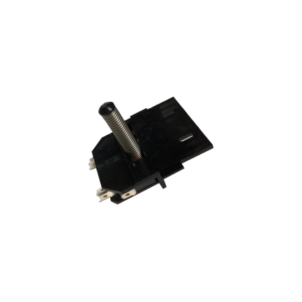
Sliding gate operator limit sensor -Spring
A sliding gate operator limit sensor with a spring mechanism (also known as a mechanical limit switch or spring limit switch) is a common type of sensor used in automatic sliding gate systems to define the gate's fully open and fully closed positions. Here's how it works and what its characteristics are: Purpose of a Limit Sensor: For any automatic gate operator, the system needs to know exactly when the gate has reached its desired open and closed positions. This is crucial for:- Stopping the Motor: Preventing the motor from continuing to run once the gate has reached its limit, which would otherwise cause damage to the gate, the motor, or the track.
- Safety: Ensuring the gate stops precisely where it should, preventing it from hitting obstacles or over-extending.
- Proper Operation: Allowing for features like auto-closing, pedestrian mode, and proper synchronization if it's a dual-gate system.
- Components: A spring limit switch typically consists of:
- A microswitch (an electrical switch that requires very little force to operate).
- A spring-loaded lever, arm, or plunger connected to the microswitch.
- A mounting bracket to attach it to the gate operator or gate frame.
- Mounting: The spring limit switch is usually positioned on the gate operator itself, or on a bracket near the motor.
- Interaction with the Gate:
- On the sliding gate itself, usually along the gear rack or a specific part of the gate frame, two small "stop" tabs or flags are installed – one for the open limit and one for the close limit.
- As the gate moves towards its fully open or fully closed position, one of these tabs/flags will physically contact and push against the spring-loaded lever/plunger of the limit switch.
- This physical contact compresses the spring and activates the microswitch.
- Signal to Control Board: When the microswitch is activated, it sends an electrical signal to the gate operator's main control board.
- Motor Stop: Upon receiving this signal, the control board immediately cuts power to the motor, stopping the gate precisely at that determined limit.
- Physical Contact: The defining feature is that it relies on direct physical contact and force to activate the switch.
- Reliability: Generally reliable as they are a simple mechanical system.
- Durability: Made to withstand repeated physical contact. However, over time, the spring can wear out, lose tension, or the switch itself can be damaged by repeated impacts or debris.
- Adjustability: The position of the "stop" tabs on the gate can be adjusted to fine-tune the exact open and closed positions of the gate.
- Maintenance: May require periodic checks to ensure the spring is intact, the switch is clean, and the "stop" tabs are securely in place and correctly positioned. They can be susceptible to damage from impacts (e.g., if a child's toy or a pet gets in the way of the stop tab).
- Compared to Magnetic Limit Switches:
- Magnetic Limit Switches: These are more common in newer and higher-end gate operators (like many BFT Deimos "Ultra" models). They use magnets attached to the gate and magnetic sensors (reed switches or Hall effect sensors) on the operator. They offer a "contactless" operation, which generally leads to less wear and tear, greater precision, and less susceptibility to environmental debris or physical impact damage.
- Spring/Mechanical Limit Switches: Are typically more cost-effective and simpler in design. They are still widely used, especially in more budget-friendly or older gate operator models.
Delay relay 0.5 Sec – AC 24 V to DC 12 V
Ship or pick up from our office.
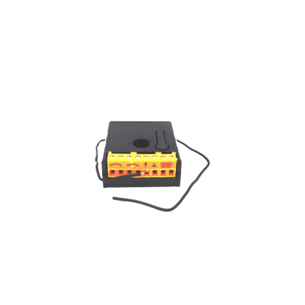
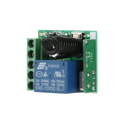
Delay relay 0.5 Sec - AC 24 V to DC 12 V
A "delay relay 0.5 Sec - AC 24 V to DC 24 V" is a time delay relay that is designed to:- Operate with a control voltage of 24 volts, which can be either Alternating Current (AC) or Direct Current (DC). This dual compatibility (AC/DC 24V) is a key feature, as many relays are specific to one type of current.
- Introduce a delay of 0.5 seconds before its contacts change state. This delay can be an "on-delay" (contacts close/open after 0.5 seconds when power is applied) or an "off-delay" (contacts remain closed/open for 0.5 seconds after power is removed), or other timing functions depending on the specific relay's design.
- Switch or control a separate circuit, which may be a 24V DC circuit. The "AC 24V to DC 24V" in the description refers to the relay's input power compatibility (it can be powered by either 24V AC or 24V DC) and its output capability (it's often used to control 24V DC loads). It is not a direct AC to DC converter for the load it's switching, but rather indicates its flexible control voltage. The relay itself doesn't convert the power; it merely switches it on or off after a delay. If the controlled circuit specifically requires DC, the relay's contacts would simply switch the 24V DC power to that circuit.
- Prevent false triggering: A brief fluctuation in voltage or a momentary signal might cause immediate activation in a standard relay. A short delay (like 0.5 seconds) can prevent such nuisance activations.
- Create timed sequences: In automated processes, certain steps may need to occur in a specific order with set delays in between. For example, a delay relay could ensure one motor starts before another or that a safety purge cycle completes before a furnace ignites.
- Control motor starts/stops: They can be used for "soft starting" motors, gradually increasing voltage to reduce inrush current, or for ensuring a motor has fully stopped before another action begins.
- HVAC systems: They prevent "short cycling" of compressors, which can damage the unit, by introducing a delay between successive starts.
- Lighting control: Ensuring lights stay on for a set period after activation (e.g., in stairwells) or controlling emergency lighting.
- Security systems: Providing a brief delay before an alarm triggers, allowing authorized personnel to disarm the system.
- On-delay (Delay on Make): The most common type. The contacts change state only after the set time delay has elapsed after the control voltage is applied.
- Off-delay (Delay on Break): The contacts change state immediately when the control voltage is applied, but only return to their original state after the set time delay has elapsed after the control voltage is removed.
- Interval: The contacts change state immediately when the control voltage is applied, and then return to their original state after the set time delay.
- Repeat Cycle: The relay continuously cycles between on and off states with specific time delays as long as the control voltage is applied.


