Shop
Gate operator control board fuse
Ship or pick up from our office.
Gate operator control board fuse
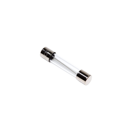
A gate operator control board fuse is a critical safety component found on the circuit board of an automatic gate system. Its primary function is to protect the electrical components of the gate operator from damage caused by excessive current, such as a short circuit or an overload. Essentially, it acts as a sacrificial link in the electrical circuit. If the current flowing through the circuit exceeds a predetermined safe limit, the thin metal wire or strip inside the fuse melts and breaks the circuit. This prevents the surge of electricity from reaching and damaging more expensive and vital components on the control board or in the motor. Types and Characteristics Gate operator control board fuses come in various amperage ratings, typically ranging from 0.2 to 15 amps, depending on the specific gate operator model and its power requirements. Some common characteristics include:- Slow-Blow/Time-Delay Fuses: Many gate operators use "slow-blow" or "time-delay" fuses. These fuses are designed to tolerate brief, temporary current surges that often occur when motors start up without immediately blowing. They only interrupt the circuit if the overload persists for a longer duration.
- Physical Form: They can be found in various physical forms, including glass tube fuses (common in older models), blade-style automotive fuses, or sometimes as surface-mount fuses directly on the printed circuit board.
- Short Circuit: A direct path for current to flow, bypassing the normal resistance, causing a sudden and large surge.
- Overload: The gate motor or another component drawing more current than it's designed for, perhaps due to mechanical obstruction, a faulty motor, or issues with the gate's movement (e.g., binding hinges, gate dragging on the ground).
- Component Failure: A faulty component on the control board or within the gate operator system itself can cause an abnormal current draw, leading the fuse to blow.
- Power Surges: External power surges from the main electrical supply or lightning strikes can also cause fuses to blow.
- Disconnect Power: Always disconnect all power to the gate operator before attempting any inspection or repair. This includes both AC power and any battery backup systems.
- Locate the Fuse: The fuse is typically located directly on the main control board, often in a small holder or a clear cover. Refer to your gate operator's manual for its exact location.
- Inspect the Fuse:
- For glass tube fuses, you can often visually inspect the wire inside; if it's broken or discolored, the fuse is blown.
- For blade-style fuses, there might be a visible break in the metal strip, or you can use a multimeter set to continuity mode. A blown fuse will show no continuity.
- Replace the Fuse: If the fuse is blown, replace it with a new fuse of the exact same amperage (ampere) and voltage rating. Using a fuse with a higher rating can lead to damage to the control board or other components, as it won't blow when it should. Using a lower rating may cause the fuse to blow unnecessarily.
Sliding gate support roller
Ship or pick up from our office.
Sliding gate support roller
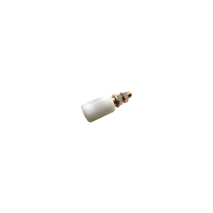
Sliding gate roller guides are essential components of sliding gates that facilitate smooth and controlled movement along a track or rail.
They help the gate stay aligned, preventing it from wobbling or coming off the track during operation. These guides are typically comprised of a bracket (often L-shaped) and one or more rollers, often made of nylon, that minimize friction and ensure quiet, efficient gate movement.
Key functions of sliding gate roller guides:
-
Smooth & Stable Movement:They ensure the gate slides smoothly along the track, preventing jerky movements and noise.
-
Alignment & Stability:They keep the gate aligned with the track, preventing it from wobbling or falling off.
-
Reduced Friction:The rollers minimize friction between the gate and the track, improving the gate's efficiency and lifespan.
-
Enhanced Durability:By reducing friction and stress on the gate and its components, they contribute to the longevity of the entire system.
Types of Sliding Gate Roller Guides:
-
L-Shaped Bracket with Rollers:This is a common type, featuring an L-shaped bracket that can be mounted on a post and nylon rollers that guide the gate.
-
Cantilever Gate Rollers:Specifically designed for cantilever gates (those that don't require a bottom track), these rollers provide support and smooth movement.
-
Adjustable Rollers:Some guides allow for horizontal adjustment of the roller position to accommodate different gate widths.
-
Flat Mount Wheels:Used when there's no need for a wheel cutout, these screw directly onto the bottom rail of the gate.
Materials and Construction:
-
Rollers:Typically made of nylon or other durable materials that can withstand wear and tear.
-
Brackets:Often made of steel (galvanized or stainless steel) for strength and durability.
Applications:
Sliding driveway gates, Security gates, Garden gates, Barn doors, Garage doors, Sheds, and Storage spaces.
In essence, sliding gate roller guides are critical for the proper functioning and longevity of sliding gates, ensuring smooth, reliable, and quiet operation.
Diode 1N5408
Ship or pick up from our office.
Diode 1N5408
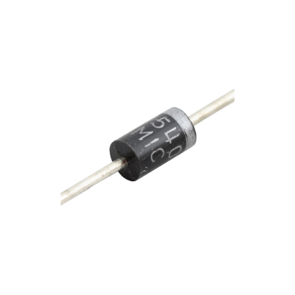
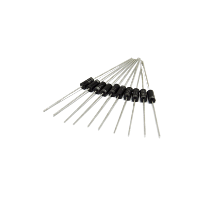
The 1N5408 is a common general-purpose rectifier diode. It's designed to allow electric current to flow primarily in one direction, making it crucial for converting alternating current (AC) to direct current (DC). Think of it like a one-way valve for electricity. It belongs to the 1N540x series of power diodes, known for their ability to handle relatively high current and voltage. Here are its key characteristics and common uses: Key Features- High Reverse Voltage Rating: It can withstand a maximum repetitive reverse voltage () of 1000V. This means it can block high voltages when current tries to flow in the "wrong" direction.
- High Forward Current Capacity: It's rated for an average rectified forward current () of 3 Amperes (A). This indicates it can handle a significant amount of current flowing through it in the correct direction.
- High Surge Current Capability: The 1N5408 can handle non-repetitive peak forward surge currents () of up to 200A for short durations, protecting circuits from sudden power spikes.
- Low Forward Voltage Drop: When conducting, it has a relatively low forward voltage drop () of approximately 1.0V to 1.2V at its rated current. A lower voltage drop means less power is lost as heat.
- Standard Recovery: It's a "standard recovery" diode, meaning its switching speed is relatively slow compared to fast recovery diodes. This makes it suitable for power rectification at lower frequencies (like 50/60 Hz AC).
- DO-201 Package: It typically comes in a DO-201 axial-leaded package, which is a through-hole component with leads extending from both ends, allowing for easy mounting on circuit boards.
- Wide Operating Temperature Range: It can operate and be stored in a wide temperature range, typically from -65°C to +175°C.
- Power Supplies and Rectifiers: This is its primary application. It efficiently converts AC input voltage into pulsating DC, which can then be smoothed by capacitors to provide a stable DC output for electronic devices. This includes full-wave and half-wave rectifier circuits.
- Battery Chargers: Used to convert AC wall power into DC for charging batteries.
- Voltage Regulation Circuits: Helps in maintaining a stable output voltage by rectifying current.
- Protection Circuits: Its ability to block reverse current makes it useful for reverse polarity protection, preventing damage to sensitive components if the power supply is connected incorrectly.
- Freewheeling Diode: Used in inductive circuits (like those with relays or motors) to provide a path for stored energy to dissipate when the current is switched off, preventing voltage spikes that could damage other components.
- Voltage Doubler Circuits: Can be used in circuits designed to effectively double the input voltage.

RFID Tag Access Control
Ship or pick up from our office.
RFID Tag Access Control
RFID Tag Access Control is a system that uses Radio Frequency Identification (RFID) technology to manage and control access to physical spaces or logical systems. It allows only authorized individuals or items to enter secure areas by wirelessly reading data stored on RFID tags. Think of it as a modern, electronic key system where your "key" is an RFID tag (like a card or key fob) and the "lock" is an RFID reader. How it Works ⚙️ The fundamental principle is straightforward:- RFID Tag/Credential: Each authorized individual or item is assigned an RFID tag. This tag contains a microchip that stores a unique identification code and an antenna.
- RFID Reader: A reader (also called an interrogator) is installed at the access point (e.g., a door, gate, or turnstile). The reader emits radio waves.
- Communication: When an RFID tag comes within range of the reader's radio waves, the tag's antenna captures energy from the reader's signal (for passive tags) or uses its own power source (for active tags) to activate its microchip. The tag then transmits its unique data back to the reader.
- Data Processing: The reader decodes the information from the tag and sends it to a central access control software or system.
- Authentication and Decision: The software compares the tag's unique ID with a database of authorized users and their assigned permissions. If the ID is valid and the user has permission to access that specific area at that time, the system sends a signal to unlock the door, open the gate, or grant access. If not, access is denied.
- Logging: The system typically logs every access attempt (both granted and denied), providing an audit trail for security monitoring and compliance.
- RFID Tag Access Controls/Credentials: These are the physical devices carried by users. They come in various forms, such as:
- Cards: Similar to credit cards, commonly used for employee badges or hotel key cards.
- Key Fobs: Small, convenient devices attached to keychains.
- Wristbands: Often used in recreational facilities or for events.
- Stickers/Labels: Can be affixed to items or vehicles.
- Mobile Credentials: Increasingly, smartphones can act as RFID tags through NFC (Near Field Communication), a subset of HF RFID.
- RFID Readers: Devices that emit radio waves to energize and read data from RFID tags. They can be fixed (at entry points) or mobile (handheld scanners).
- Antennas: Integral to the reader (or external), they transmit and receive radio signals to and from the tags. The antenna design influences the read range and reliability.
- Access Control Software/Management System: The "brain" of the system. This software manages user databases, assigns access permissions, logs events, and allows administrators to configure and monitor the system remotely.
- Access Control Panel/Controller: Hardware that connects the readers to the central software, processing data and controlling the locking mechanisms.
- Passive RFID Tags:
- Do not have an internal power source.
- They draw power from the radio waves emitted by the reader to operate.
- Are generally smaller, less expensive, and require no maintenance.
- Have a shorter read range (a few centimeters to a few feet).
- Most commonly used in access control for cards and key fobs.
- Active RFID Tags:
- Have their own internal power source (battery).
- Can transmit data over longer distances (up to several hundred meters) and at regular intervals.
- Are larger and more expensive.
- Often used for long-range applications like vehicle tracking or asset management.
- Semi-Passive RFID Tags (Battery-Assisted Passive - BAP):
- Contain a battery to power the microchip, but still rely on the reader's signal to initiate communication.
- Offer better read range and performance than passive tags, without continuously transmitting like active tags.
- Low Frequency (LF) RFID (125-134 kHz):
- Short read range (1-10 cm).
- Less susceptible to interference from metal and water.
- Common in traditional access control systems.
- High Frequency (HF) RFID (13.56 MHz):
- Moderate read range (10 cm-1 meter).
- Widely used for access control, ticketing, and Near Field Communication (NFC) applications (like smartphone taps).
- Ultra-High Frequency (UHF) RFID (300 MHz-3 GHz, often 860-960 MHz for RAIN RFID):
- Long read range (up to 12 meters).
- More susceptible to interference from liquids and metals.
- Used in applications requiring longer read distances, such as vehicle access control or large-scale inventory tracking.
Relay Mini PCB 5-Pin 10A
Ship or pick up from our office.
Relay Mini PCB 5-Pin 10A
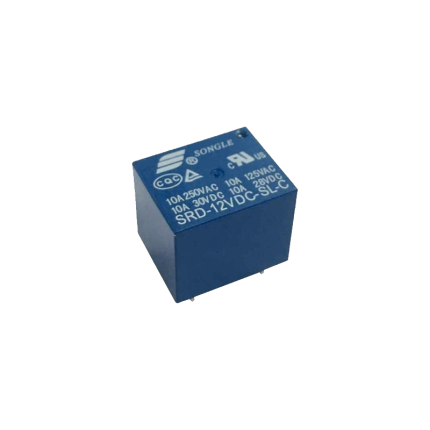
A Relay Mini PCB 5-Pin 10A is a compact, electromechanical switch designed to be mounted directly onto a printed circuit board (PCB). It uses a small control voltage to switch a larger current, making it useful for isolating control circuits from power circuits or for switching higher-power loads with a low-power signal. Key Features and Specifications- Mini: This indicates its small physical size, making it suitable for applications where space is limited.
- PCB: This means it's designed for Printed Circuit Board mounting. Its pins are typically configured to be soldered directly into holes on the PCB.
- 5-Pin: These five pins usually consist of:
- Two pins for the coil: These are where the control voltage is applied to energize the coil and activate the relay.
- Three pins for the contacts: These typically include a common (COM) pin, a normally open (NO) pin, and a normally closed (NC) pin.
- 10A: This is the maximum current rating that the relay's contacts can safely switch. It means the relay is capable of handling up to 10 amperes of current through its switched contacts.
- Normally Open (NO): The contact is open when the coil is de-energized and closes when the coil is energized.
- Normally Closed (NC): The contact is closed when the coil is de-energized and opens when the coil is energized.
- Automotive applications: For controlling lights, motors, and other accessories.
- Home automation: Switching lights, appliances, and HVAC systems.
- Industrial control: In PLCs (Programmable Logic Controllers) and other control panels.
- Appliance control: In washing machines, refrigerators, and microwave ovens.
- DIY electronics projects: Where low-power signals need to control higher-power devices.
Diode 1N4007
Ship or pick up from our office.
Diode 1N4007
The 1N4007 is a very common and versatile silicon rectifier diode. It's part of the 1N400x series of general-purpose diodes, with the "7" indicating its specific voltage rating. Key Characteristics- Rectifier Diode: Its primary function is to convert alternating current (AC) into pulsating direct current (DC) by allowing current to flow in only one direction.
- High Reverse Voltage Rating: The 1N4007 can withstand a peak repetitive reverse voltage () of 1000V. This makes it suitable for high-voltage applications.
- Average Forward Current: It can handle an average forward current () of 1 Ampere (1A).
- Forward Voltage Drop: When conducting in the forward direction, it has a relatively low forward voltage drop () of approximately 0.7V to 1.1V. This voltage drop represents the power lost within the diode.
- Surge Current Capability: It can handle a non-repetitive peak surge current () of up to 30A for short durations, which is useful for handling initial power-on surges.
- Package Type: It typically comes in a DO-41 axial-lead package, which is a small, cylindrical plastic package with leads on both ends.
- Operating Temperature Range: It operates reliably over a wide temperature range, typically from -55°C to +175°C.
- Forward Bias: When a positive voltage is applied to the anode (P-side) and a negative voltage to the cathode (N-side), the diode is forward-biased. If the applied voltage exceeds the forward voltage drop (around 0.7V for silicon diodes), the diode conducts, allowing current to flow from anode to cathode.
- Reverse Bias: When a negative voltage is applied to the anode and a positive voltage to the cathode, the diode is reverse-biased. In this state, the diode acts like an open switch, blocking current flow. The 1N4007 is designed to withstand up to 1000V in this reverse-biased state before breaking down.
- Rectifier Circuits:
- Half-wave and Full-wave Rectifiers: Essential for converting AC power from the mains (like in household appliances) to DC power for electronic devices.
- Bridge Rectifiers: Used to convert the entire AC waveform into pulsating DC, achieving more efficient rectification.
- Power Supplies: Used for rectifying the AC input in power supply units to provide DC voltage to various components.
- Voltage Protection:
- Reverse Polarity Protection: Prevents damage to circuits if the power supply is connected with incorrect polarity.
- Freewheeling Diodes (Flyback Diodes): Protect sensitive components from voltage spikes generated by inductive loads (like relays, motors, and solenoids) when their magnetic field collapses.
- Voltage Spike Suppression: Helps to suppress transient voltage spikes that can occur due to switching events or lightning, safeguarding delicate electronics.
- Inverters and Converters: Used in various power conversion circuits.
- Current Flow Regulation: Can be used in simple current limiting or flow control applications.


