Shop
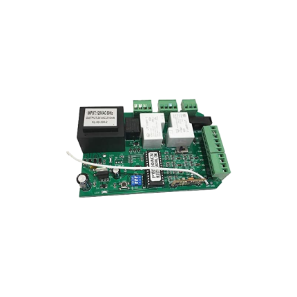
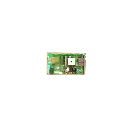
Sliding gate operator control board SLRG110
Ship or pick up from our office.
Sliding gate operator control board SLRG110
The SLRG110 is a universal main control board for sliding gate operators that runs on 110-volt AC power.
It acts as the "brain" of a sliding gate system, managing its core functions.
Here's a breakdown of what the SLRG110 offers:
Core Functionality
- Motor Control: It receives signals from various access devices (like remote controls or keypads) and translates them into commands to control the gate's motor, initiating opening, closing, and stopping movements.
- Power Management: It receives power from a 110V AC source and directs it to the gate motor and other connected accessories.
- Adjustable Settings: The board typically allows for customization of gate operation, including:
- Adjustable speed settings for both opening and closing.
- Adjustable auto-close timer (e.g., 0, 30, 60, 90 seconds).
- Adjustable torque and closing force to suit different gate weights and preferences.
- Ability to add and delete remote controls easily.
- Option to set auto-close when power is restored after an outage.
Key Features & Safety
- Obstruction Detection: A crucial safety feature, the SLRG110 can detect obstructions in the gate's path during movement and automatically stop or reverse the gate to prevent damage or injury.
- This often utilizes infrared detection connectors for photocells.
- Remote Control Capability: It's designed to work seamlessly with remote controls for convenient operation.
- Emergency Release: The system usually includes an emergency release key for manual operation in case of power failure.
- Limit Switches: It connects to limit switches (often magnetic) that define the gate's fully open and closed positions, preventing overtravel.
- Accessory Inputs: The board has various input terminals for connecting additional accessories like:
- Photocells (safety beams)
- Manual push buttons
- Wired keypads
- GSM inputs (for remote access via mobile networks)
- Vehicle sensor exit wands
Universal Compatibility
The SLRG110 is considered a universal control board, meaning it's designed to be compatible with a wide range of sliding gate opener models.
This makes it a versatile replacement option for existing systems. It can operate gates weighing up to approximately 1750-1760 lbs.
Sliding gate operator gear
Ship or pick up from our office.
Sliding gate operator gear
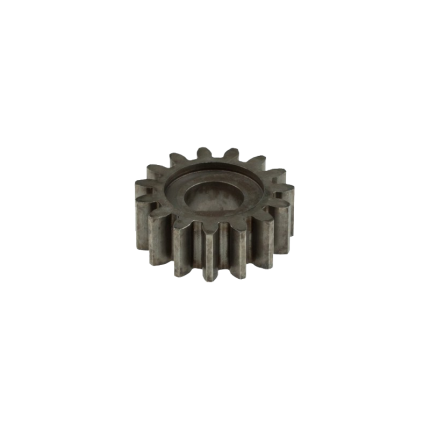
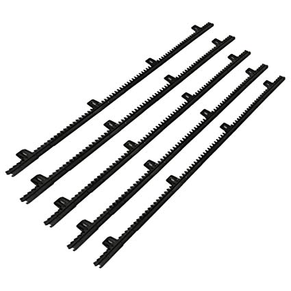
The sliding gate operator gear is a crucial component within an automatic sliding gate system. It's essentially the mechanism that translates the rotational power from the electric motor into the linear motion needed to open and close a sliding gate. Here's how it generally works:- Pinion Gear: Inside the gate operator's housing, there's a pinion gear. This is a small, typically round gear directly connected to the motor. When the motor turns, it rotates the pinion gear.
- Rack Gear: Attached to the bottom edge of the sliding gate itself is a rack gear. This is a long, straight bar with teeth that mesh with the teeth of the pinion gear.
- Translating Motion: As the motor spins the pinion gear, its teeth engage with the teeth on the rack gear. This engagement causes the rack gear (and thus the entire gate) to move horizontally along its track. It's similar to how a train moves along a toothed railway or a car's steering rack works.
Sliding gate operator gear
Ship or pick up from our office.
Sliding gate operator gear
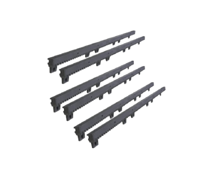
A sliding gate operator gear refers to the toothed gear or rack and pinion system that facilitates the movement of a sliding gate.
This system typically consists of a toothed metal bar (the rack) attached to the gate and a motorized pinion gear that engages with the rack, causing the gate to slide open and closed.
Here's a more detailed explanation:
-
Rack:This is a toothed bar, usually made of steel or nylon-reinforced steel, mounted along the bottom of the sliding gate.
-
Pinion Gear:This gear is connected to the motor of the gate operator. When the motor rotates, the pinion gear engages with the rack's teeth, causing the gate to move.
-
Operation:The rotation of the pinion gear drives the gate along the track, either opening or closing it, depending on the direction of rotation.
-
Materials:While some racks are made of all-metal, nylon racks with a steel core are popular due to their lightweight nature, durability, and resistance to rust and wear.
Sliding gate operator gear rack -SLGR2
Ship or pick up from our office.
Sliding gate operator gear rack -SLGR2
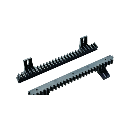
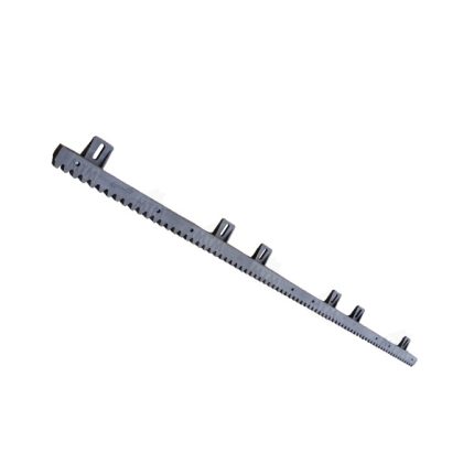
The Sliding Gate Operator Gear Rack SLGR2 is a specific type of toothed bar used in conjunction with a sliding gate operator (motor) to convert its rotational power into the linear motion needed to open and close a sliding gate. Let's break down what SLGR2 likely refers to and its characteristics: Function of a Gear Rack:- Linear Motion: The Sliding Gate Operator Gear Rack SLGR2 is essentially a straight "rack" of teeth that meshes with a small circular gear called a pinion, which is attached to the shaft of the sliding gate operator's motor.
- Power Transmission: As the pinion spins, its teeth engage with the teeth of the gear rack, pushing or pulling the gate horizontally along its track. This is how the motor physically moves the gate.
- Length: The Sliding Gate Operator Gear Rack SLGR2 is specified as being 340 mm (millimetres) in length. This is a relatively short segment. Sliding gates often require multiple sections of gear rack to be joined together to span the entire length of the gate, as most gates are much longer than 340mm.
- Mounting Holes: It has "2 Holes". These holes are pre-drilled for easy attachment to the bottom frame of the sliding gate using screws or bolts.
- Material: While the exact material for this specific SLGR2 is not explicitly stated in all listings, gear racks are commonly made from:
- Steel (most common): Offers high strength, durability, and resistance to wear, making it suitable for heavy gates and high-traffic applications. Often galvanized or treated for corrosion resistance.
- Nylon with a Steel Core: A popular alternative. The nylon exterior provides quieter operation and good corrosion resistance, while the internal steel core offers the necessary strength and stability for the gate's weight and movement. This is a good balance of properties.
- Less commonly, other plastics or stainless steel are used for specific applications.
- "Module": While not explicitly stated for SLGR2, gear racks (and their mating pinions) adhere to a "module" standard (e.g., Module 2, Module 4). The module defines the size of the teeth and the spacing between them, ensuring that the gear rack properly meshes with the pinion gear of the specific sliding gate operator it's intended for. The SLGR2 would have a specific module that matches the operators sold by Royal Gate.
Sliding gate operator gear rack -SLGR41
Ship or pick up from our office.
Sliding gate operator gear rack -SLGR41
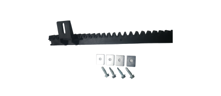
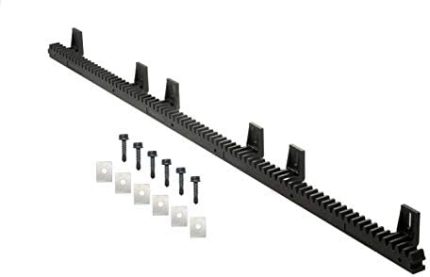
*4 Holes *Length: 1018 mmSliding gate operator gear rack -SLGR611
Ship or pick up from our office.
Sliding gate operator gear rack -SLGR611
*6 Holes *Length: 1018 mmSliding gate operator gear rack -SLGR612
Ship or pick up from our office.
Sliding gate operator gear rack -SLGR612
*6 Holes *Length: 1018 mmSliding gate operator limit sensor – Magnetic mechanism
Ship or pick up from our office.
Sliding gate operator limit sensor - Magnetic mechanism
A sliding gate operator limit sensor, often a limit switch, is a crucial component that signals the gate operator when the gate has reached its fully open or fully closed position, stopping the motor and preventing over-travel. These sensors ensure the gate stops at the correct positions, preventing damage to the gate and surrounding structure.
Here's a more detailed explanation:
-
Function:Limit sensors, like limit switches, detect when the gate reaches its extreme open or closed positions.
-
How it works:When the gate reaches the limit, the sensor sends a signal to the gate operator's control board, which then stops the motor.
-
Importance:Without limit sensors, the gate might continue to move, potentially hitting the end posts or other obstructions, causing damage.
-
Types:Common types include magnetic limit switches and photoelectric sensors (photo eyes).
-
Magnetic Limit Switches:These utilize magnets placed on the gate and a magnetic sensor on the operator. When the magnet aligns with the sensor, it triggers the limit switch.
-
Photoelectric Sensors (Photo Eyes):These use infrared beams to detect obstructions. When the beam is broken (e.g., by the gate), the sensor signals the operator to stop.
-
Installation:Proper installation and adjustment of limit sensors are crucial for the reliable operation.
-
Maintenance:Regular inspection and maintenance of limit sensors are recommended, as they can wear out or become misaligned over time.
Sliding gate operator limit sensor -Spring
Ship or pick up from our office.
Sliding gate operator limit sensor -Spring
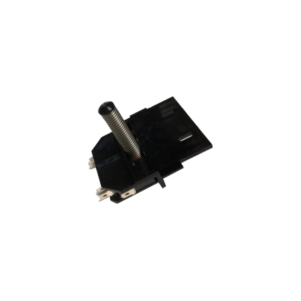
A sliding gate operator limit sensor with a spring mechanism (also known as a mechanical limit switch or spring limit switch) is a common type of sensor used in automatic sliding gate systems to define the gate's fully open and fully closed positions. Here's how it works and what its characteristics are: Purpose of a Limit Sensor: For any automatic gate operator, the system needs to know exactly when the gate has reached its desired open and closed positions. This is crucial for:- Stopping the Motor: Preventing the motor from continuing to run once the gate has reached its limit, which would otherwise cause damage to the gate, the motor, or the track.
- Safety: Ensuring the gate stops precisely where it should, preventing it from hitting obstacles or over-extending.
- Proper Operation: Allowing for features like auto-closing, pedestrian mode, and proper synchronization if it's a dual-gate system.
- Components: A spring limit switch typically consists of:
- A microswitch (an electrical switch that requires very little force to operate).
- A spring-loaded lever, arm, or plunger connected to the microswitch.
- A mounting bracket to attach it to the gate operator or gate frame.
- Mounting: The spring limit switch is usually positioned on the gate operator itself, or on a bracket near the motor.
- Interaction with the Gate:
- On the sliding gate itself, usually along the gear rack or a specific part of the gate frame, two small "stop" tabs or flags are installed – one for the open limit and one for the close limit.
- As the gate moves towards its fully open or fully closed position, one of these tabs/flags will physically contact and push against the spring-loaded lever/plunger of the limit switch.
- This physical contact compresses the spring and activates the microswitch.
- Signal to Control Board: When the microswitch is activated, it sends an electrical signal to the gate operator's main control board.
- Motor Stop: Upon receiving this signal, the control board immediately cuts power to the motor, stopping the gate precisely at that determined limit.
- Physical Contact: The defining feature is that it relies on direct physical contact and force to activate the switch.
- Reliability: Generally reliable as they are a simple mechanical system.
- Durability: Made to withstand repeated physical contact. However, over time, the spring can wear out, lose tension, or the switch itself can be damaged by repeated impacts or debris.
- Adjustability: The position of the "stop" tabs on the gate can be adjusted to fine-tune the exact open and closed positions of the gate.
- Maintenance: May require periodic checks to ensure the spring is intact, the switch is clean, and the "stop" tabs are securely in place and correctly positioned. They can be susceptible to damage from impacts (e.g., if a child's toy or a pet gets in the way of the stop tab).
- Compared to Magnetic Limit Switches:
- Magnetic Limit Switches: These are more common in newer and higher-end gate operators (like many BFT Deimos "Ultra" models). They use magnets attached to the gate and magnetic sensors (reed switches or Hall effect sensors) on the operator. They offer a "contactless" operation, which generally leads to less wear and tear, greater precision, and less susceptibility to environmental debris or physical impact damage.
- Spring/Mechanical Limit Switches: Are typically more cost-effective and simpler in design. They are still widely used, especially in more budget-friendly or older gate operator models.
Sliding gate operator limit stopper bracket
Ship or pick up from our office.
Sliding gate operator limit stopper bracket
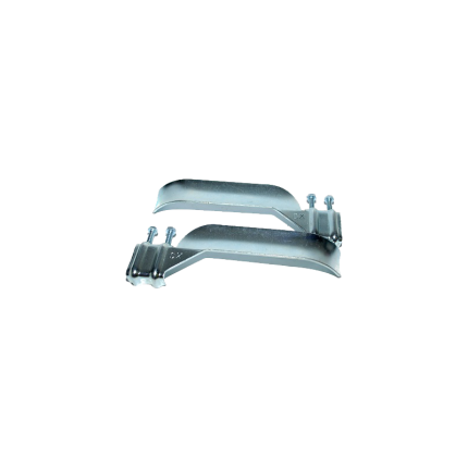
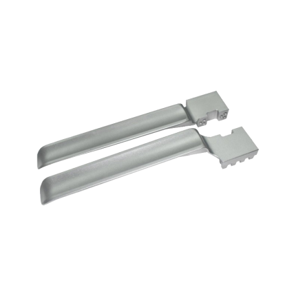
The gate operator system with a damaged limit stopper bracket can not work properly, and it will soon stop working. Most of the time, the main control board and the motor will be damaged because of this issue and have to be replaced. Sometimes errors come from the limit stopper bracket not working because they are damaged and needs only to be cleaned or readjustment.A sliding gate operator limit stopper bracket is a component that works with limit switches to prevent a sliding gate from over-extending its travel, ensuring it stops at the desired open and closed positions.
These brackets typically hold magnets or other sensor components that interact with the limit switches on the gate operator's control board. They help maintain the gate's smooth and safe operation by preventing it from hitting obstructions or going off its track.
Here's a more detailed explanation:
-
Purpose:The primary function of the limit stopper bracket is to define the boundaries of the gate's movement. It ensures the gate stops at the fully open and fully closed positions, preventing it from over-traveling.
-
How it works:The bracket holds a magnetic or other type of sensor that is triggered when the gate reaches its limit. This trigger sends a signal to the gate operator's control board, which then stops the motor.
-
Components:
- Bracket: The physical structure that holds the sensor.
- Sensor: A device (often a magnet) that interacts with the limit switch.
- Limit Switch: A switch on the gate operator's control board that is activated by the sensor.
- Bracket: The physical structure that holds the sensor.
-
Importance:
- Safety: Prevents the gate from hitting objects or going off track, reducing the risk of damage or injury.
- Reliability: Ensures consistent and reliable gate operation by defining the travel limits.
- Protection: Protects the gate, operator, and surrounding objects from damage due to over-travel.
- Safety: Prevents the gate from hitting objects or going off track, reducing the risk of damage or injury.

