Shop
Door Strike Lock
Ship or pick up from our office.
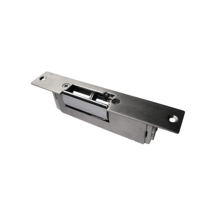
Door Strike Lock
*Fail-Secure/Fail-Safe *Capacity: 100 Kg *DC 12 VAn electric strike is an electromechanical lock release device that replaces a standard door strike plate.
It allows a door to be opened remotely, typically via an access control system, without manually retracting the latch. When activated, the electric strike releases the latch, enabling the door to be opened.
Here's a more detailed explanation:
Functionality:
-
Replaces Standard Strike:Electric strikes are installed in the door frame, taking the place of the standard strike plate.
-
Remote Release:They are designed to work with various access control systems, such as keypads, card readers, or intercoms.
-
Activation:When an authorized signal is received (e.g., a code is entered, a card is swiped), the electric strike releases the latch, allowing the door to be opened.
-
Fail-Safe or Fail-Secure:Electric strikes can be configured in either a fail-safe or fail-secure mode.
- Fail-safe: In this mode, the door unlocks when power is lost, making it suitable for safety applications where access is needed during power outages.
- Fail-secure: In this mode, the door remains locked when power is lost, requiring power to unlock, making it suitable for high-security applications.
How it Works:
- The electric strike contains a solenoid, which is an electromagnet.
- When the solenoid is activated by an electrical signal, it moves a component (like an armature) that allows the latch to move freely.
- This movement releases the door, allowing it to be opened.
Key Differences from Other Locks:
-
Electric vs. Magnetic Locks:Unlike magnetic locks, which use powerful magnets to hold the door closed, electric strikes release the latch mechanism.
-
Remote Access:Electric strikes offer remote access control, allowing doors to be unlocked without manual intervention.
-
Versatility:They can be used with various locking mechanisms, including cylindrical, mortise, and rim exit devices.
Common Applications:
-
Access Control:Electric strikes are a core component of access control systems in commercial and residential settings.
-
Security:They provide a higher level of security compared to standard locks, especially when used with fail-secure configurations.
-
Safety:In fail-safe configurations, they ensure safe egress during emergencies.
-
Specific Areas:They are commonly found in reception areas, daycare centers, and other locations where controlled access is needed.
Safety Sensor P52000H
Ship or pick up from our office.
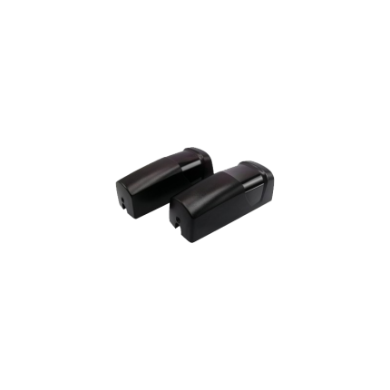
Safety Sensor P52000H
IP Rating: IP54
Certification: CE
Working Voltage: 12V-24V AC/DC
Temperature Rane: -20ºC to 60 ºC
Protection Index: IP54
Photocell Wavelength: 940nm
Receiver Range: More Than 12m
Weight: 139g
A gate opener safety sensor is a crucial component of automated gate systems designed to prevent accidents and damage by detecting obstructions in the gate's path.
These sensors, often photoelectric, use an infrared beam to monitor the area and trigger the gate to stop or reverse if something is blocking its movement.
How it works:
-
Transmitter and Receiver:A safety sensor typically consists of a transmitter that emits an infrared light beam and a receiver that detects the beam.
-
Obstruction Detection:When an object, person, or vehicle interrupts the beam, the receiver signals the gate operator to stop or reverse the gate's movement.
-
Safety Feature:This mechanism prevents the gate from closing on anything or anyone, ensuring safety and preventing potential damage.
Types of Safety Sensors:
-
Photoelectric Sensors (Photo Eyes):These are the most common type, using an infrared beam to detect obstructions.
-
Safety Edges:These sensors are typically placed along the edge of the gate and trigger a stop or reverse when they encounter pressure.
-
Induction Loops:These sensors are embedded in the ground and detect vehicles as they pass over them, triggering the gate to open or close.
Importance:
-
Safety:The primary function is to prevent accidents and injuries by stopping or reversing the gate when an obstruction is present.
-
Preventing Damage:By detecting obstructions, these sensors help avoid damage to the gate, vehicles, or anything else in its path.
-
Compliance:Safety sensors are often required for automated gates to meet safety regulations and standards.
Common Issues:
-
Misalignment:If the sensor is misaligned, the infrared beam may not reach the receiver, causing the gate to malfunction.
-
Obstructions:Debris, dirt, or other obstructions can interfere with the beam and trigger false alarms.
-
Sensor Failure:Like any electronic device, sensors can fail over time, requiring replacement.
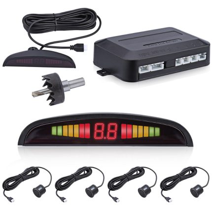
Car parking sensor kit
Gate operator capacitor
Ship or pick up from our office.
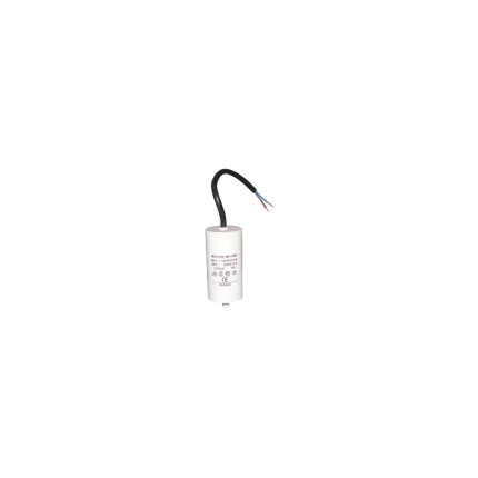
Gate operator capacitor
A gate operator capacitor is an electrical component that assists the motor in a gate opener system to start and run smoothly.
It stores and releases electrical energy to provide the initial torque needed to get the motor going and to ensure consistent operation. These capacitors are crucial for both swing and sliding gate openers that are powered by AC.
Here's a more detailed explanation:
-
Starting the Motor:When a gate opener is activated, the motor needs a significant amount of power to begin rotating. The capacitor provides a burst of electrical energy to help the motor overcome its inertia and start moving.
-
Maintaining Smooth Operation:Once the motor is running, the capacitor helps to smooth out the electrical current, ensuring consistent and efficient operation. This prevents the motor from stalling or experiencing performance issues due to voltage fluctuations.
-
Types of Capacitors:Gate operator capacitors can be categorized as either start capacitors or run capacitors.
- Start capacitors: are used to provide the initial surge of power needed to get the motor rotating.
- Run capacitors: help to maintain consistent motor performance during operation.
- Start capacitors: are used to provide the initial surge of power needed to get the motor rotating.
-
Common Applications:Capacitors are used in various gate operator systems, including:
- Swing gate openers
- Sliding gate openers
- Commercial and residential gate systems
- Barrier arms
- Overhead doors
- Swing gate openers
-
Compatibility:Different gate operators may require specific types and sizes of capacitors, so it's important to choose the right replacement capacitor for your system.
Radio receiver RX2CH-Multi Code
Ship or pick up from our office.
Radio receiver RX2CH-Multi Code
(Compatible with the wireless keypad control KW402 & KW125 *#8) *COMPATIBILITY LIST: NICE, FAAC, Liftmaster, Sommer, Ditec, V2, Marantec, etc... *AC/DC 12-24 V *2 Channels *AM/FM 300-869 MHz *Capacity: Unlimited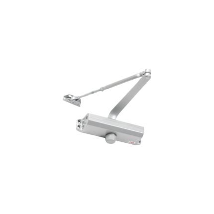
Door closer -DCL061
Ship or pick up from our office.
Door closer -DCL061
The "Door closer -DCL061" appears to refer to a specific model of door closer, primarily offered by Royal Electronics Technology Center Co. Based on the information found, here's what we know about it:- Type: DCL061 is a mechanical door closer.
- Capacity: Door closer -DCL061 has a capacity of 45 Kg, indicating it's suitable for doors up to that weight.
- Dimensions: Door closer -DCL061 dimensions are 25 × 9 × 9 cm.
- Purpose: Like all door closers, it's designed to automatically close a door in a controlled manner after it has been opened. This serves various purposes, including:
- Security: Ensuring doors are not left open inadvertently.
- Fire Safety: Crucial for fire doors to prevent the spread of fire and smoke.
- Energy Efficiency: Helping to maintain indoor temperatures by ensuring doors close properly.
- Accessibility and Safety: Preventing doors from slamming, reducing the risk of injury, and allowing controlled passage for individuals with limited mobility.
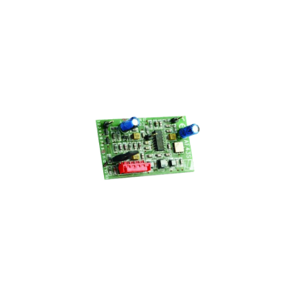
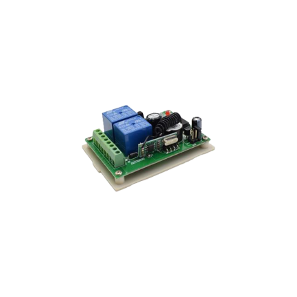
Delay relay 0.5 Sec – AC 24 V to DC 12 V
Ship or pick up from our office.
Delay relay 0.5 Sec - AC 24 V to DC 12 V
A "delay relay 0.5 Sec - AC 24 V to DC 24 V" is a time delay relay that is designed to:- Operate with a control voltage of 24 volts, which can be either Alternating Current (AC) or Direct Current (DC). This dual compatibility (AC/DC 24V) is a key feature, as many relays are specific to one type of current.
- Introduce a delay of 0.5 seconds before its contacts change state. This delay can be an "on-delay" (contacts close/open after 0.5 seconds when power is applied) or an "off-delay" (contacts remain closed/open for 0.5 seconds after power is removed), or other timing functions depending on the specific relay's design.
- Switch or control a separate circuit, which may be a 24V DC circuit. The "AC 24V to DC 24V" in the description refers to the relay's input power compatibility (it can be powered by either 24V AC or 24V DC) and its output capability (it's often used to control 24V DC loads). It is not a direct AC to DC converter for the load it's switching, but rather indicates its flexible control voltage. The relay itself doesn't convert the power; it merely switches it on or off after a delay. If the controlled circuit specifically requires DC, the relay's contacts would simply switch the 24V DC power to that circuit.
- Prevent false triggering: A brief fluctuation in voltage or a momentary signal might cause immediate activation in a standard relay. A short delay (like 0.5 seconds) can prevent such nuisance activations.
- Create timed sequences: In automated processes, certain steps may need to occur in a specific order with set delays in between. For example, a delay relay could ensure one motor starts before another or that a safety purge cycle completes before a furnace ignites.
- Control motor starts/stops: They can be used for "soft starting" motors, gradually increasing voltage to reduce inrush current, or for ensuring a motor has fully stopped before another action begins.
- HVAC systems: They prevent "short cycling" of compressors, which can damage the unit, by introducing a delay between successive starts.
- Lighting control: Ensuring lights stay on for a set period after activation (e.g., in stairwells) or controlling emergency lighting.
- Security systems: Providing a brief delay before an alarm triggers, allowing authorized personnel to disarm the system.
- On-delay (Delay on Make): The most common type. The contacts change state only after the set time delay has elapsed after the control voltage is applied.
- Off-delay (Delay on Break): The contacts change state immediately when the control voltage is applied, but only return to their original state after the set time delay has elapsed after the control voltage is removed.
- Interval: The contacts change state immediately when the control voltage is applied, and then return to their original state after the set time delay.
- Repeat Cycle: The relay continuously cycles between on and off states with specific time delays as long as the control voltage is applied.
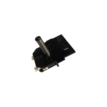
Sliding gate operator limit sensor -Spring
Ship or pick up from our office.
Sliding gate operator limit sensor -Spring
A sliding gate operator limit sensor with a spring mechanism (also known as a mechanical limit switch or spring limit switch) is a common type of sensor used in automatic sliding gate systems to define the gate's fully open and fully closed positions. Here's how it works and what its characteristics are: Purpose of a Limit Sensor: For any automatic gate operator, the system needs to know exactly when the gate has reached its desired open and closed positions. This is crucial for:- Stopping the Motor: Preventing the motor from continuing to run once the gate has reached its limit, which would otherwise cause damage to the gate, the motor, or the track.
- Safety: Ensuring the gate stops precisely where it should, preventing it from hitting obstacles or over-extending.
- Proper Operation: Allowing for features like auto-closing, pedestrian mode, and proper synchronization if it's a dual-gate system.
- Components: A spring limit switch typically consists of:
- A microswitch (an electrical switch that requires very little force to operate).
- A spring-loaded lever, arm, or plunger connected to the microswitch.
- A mounting bracket to attach it to the gate operator or gate frame.
- Mounting: The spring limit switch is usually positioned on the gate operator itself, or on a bracket near the motor.
- Interaction with the Gate:
- On the sliding gate itself, usually along the gear rack or a specific part of the gate frame, two small "stop" tabs or flags are installed – one for the open limit and one for the close limit.
- As the gate moves towards its fully open or fully closed position, one of these tabs/flags will physically contact and push against the spring-loaded lever/plunger of the limit switch.
- This physical contact compresses the spring and activates the microswitch.
- Signal to Control Board: When the microswitch is activated, it sends an electrical signal to the gate operator's main control board.
- Motor Stop: Upon receiving this signal, the control board immediately cuts power to the motor, stopping the gate precisely at that determined limit.
- Physical Contact: The defining feature is that it relies on direct physical contact and force to activate the switch.
- Reliability: Generally reliable as they are a simple mechanical system.
- Durability: Made to withstand repeated physical contact. However, over time, the spring can wear out, lose tension, or the switch itself can be damaged by repeated impacts or debris.
- Adjustability: The position of the "stop" tabs on the gate can be adjusted to fine-tune the exact open and closed positions of the gate.
- Maintenance: May require periodic checks to ensure the spring is intact, the switch is clean, and the "stop" tabs are securely in place and correctly positioned. They can be susceptible to damage from impacts (e.g., if a child's toy or a pet gets in the way of the stop tab).
- Compared to Magnetic Limit Switches:
- Magnetic Limit Switches: These are more common in newer and higher-end gate operators (like many BFT Deimos "Ultra" models). They use magnets attached to the gate and magnetic sensors (reed switches or Hall effect sensors) on the operator. They offer a "contactless" operation, which generally leads to less wear and tear, greater precision, and less susceptibility to environmental debris or physical impact damage.
- Spring/Mechanical Limit Switches: Are typically more cost-effective and simpler in design. They are still widely used, especially in more budget-friendly or older gate operator models.
Radio remote control receiver
Ship or pick up from our office.
Radio remote control receiver
One remote control is included (Compatible with Home-Link system) *DC 12-24 V *2 Channels *315 MHzA radio remote control receiver is an electronic device that receives signals from a remote control and triggers the gate's motor to open or close.
It acts as the "ear" for the gate opener, interpreting the radio signals sent by the remote. These receivers are crucial for the functionality and convenience of automated gate systems.
Here's a more detailed explanation:
Function:
- The receiver is designed to detect the specific radio frequency and code transmitted by the gate remote.
- Upon receiving the correct signal, it activates the gate's motor, causing the gate to move.
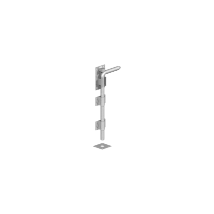
Gate drop ground latch
Ship or pick up from our office.
Gate drop ground latch
A gate drop ground latch, also known as a cane bolt or drop rod, is a mechanism used to secure a gate in the open or closed position by inserting a rod into the ground.
It's typically used for double gates to keep one side stationary while the other is latched. It helps prevent gates from moving in the wind and adds extra security.
Here's a more detailed explanation:
How it works:
- A metal rod (the drop rod or cane bolt) is attached to the gate and slides through brackets or guides.
- When the gate is in the desired position (open or closed), the rod is lowered into a hole or receiver in the ground, securing the gate.
- To open the gate, the rod is lifted out of the ground and turned out of the way.
Key features and benefits:
- Secures gates: Prevents gates from swinging open or closed due to wind or other factors.
- Versatile: Can be used on various gate types, including wood, metal, and vinyl.
- Double gate support: Especially useful for securing one side of a double gate while the other is latched.
- Added security: Can be used in conjunction with other latches for increased security.
- Easy installation: Generally involves mounting brackets and drilling a hole for the rod.
- Durable: Made of materials like steel, often with a powder coat finish for weather resistance.
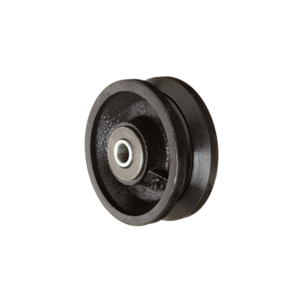
Sliding gate V-Groove wheels -SLGWS800
Ship or pick up from our office.
Sliding gate V-Groove wheels -SLGWS800
Sliding gate V-Groove wheels are a fundamental component in a common type of sliding gate system. Unlike cantilever gates that hang above the ground, these gates roll directly on a track installed on the ground. Here's a detailed explanation: What they are: A V-Groove wheel is a type of wheel specifically designed with a V-shaped groove machined into its circumference. This groove perfectly mates with a corresponding V-shaped track, which is usually made of angle iron or a similar steel profile. How they work:- Track Installation: A V-shaped steel track is securely laid and typically anchored into the driveway or ground along the entire length of the gate's travel path. This track acts as the "railroad track" for the gate.
- Wheel Attachment: The V-Groove wheels are attached to the bottom frame of the sliding gate. Depending on the gate's length and weight, multiple wheels will be strategically placed along its underside.
- Guidance and Support: As the gate opens or closes (either manually or with a gate opener), the V-shaped groove of the wheels sits snugly onto the V-shaped track. This tight fit ensures:
- Smooth and Stable Movement: The gate rolls smoothly and without wobbling or derailing.
- Guidance: The wheels effectively guide the gate in a straight line, preventing it from veering off course.
- Load Distribution: The wheels bear the weight of the gate, distributing it evenly along the track.
- Materials: V-Groove wheels are typically made from durable materials to withstand heavy loads and wear:
- Steel (most common): Offers high strength, load capacity, and durability. Often zinc-plated or galvanized for corrosion resistance.
- Cast Iron: More economical but can be more prone to breakage than steel, and may require more frequent lubrication.
- Nylon or High-Impact Polymer: Quieter in operation and excellent for corrosion resistance, but generally have lower load capacities than steel and may not last as long under heavy use.
- Bearings: High-quality V-Groove wheels incorporate sealed bearings (like precision ball bearings). These reduce friction, ensure smooth rolling, and often require no lubrication, making them "maintenance-free."
- Sizes: Available in various diameters (e.g., 3", 4", 6") and load capacities (ranging from hundreds to thousands of pounds per wheel) to suit different gate sizes and weights.
- With or Without Brackets: Some wheels come with integrated mounting brackets for easier installation, while others are just the wheel itself, requiring a custom bracket or housing.
- Stability and Alignment: The V-groove design provides excellent stability, keeping the gate perfectly aligned with the track and preventing it from tilting or derailing.
- High Load Capacity: Especially steel V-Groove wheels, they are designed to handle very heavy gates, making them suitable for large residential, commercial, and industrial applications.
- Durability and Longevity: Made from robust materials, they offer a long service life, particularly with sealed bearings.
- Relatively Simple System: The concept is straightforward, and the components are widely available.
- Ground Track Maintenance: The main drawback compared to cantilever gates is that the ground track can accumulate debris (leaves, dirt, snow, ice). This debris must be regularly cleaned to ensure smooth operation and prevent damage to the wheels or opener. In Surrey, BC's climate, this is an important consideration due to rain and potential for snow.
- Driveway Disruption: Installing a ground track requires cutting into or modifying the driveway surface.
- Noise: While smoother than some other wheel types, they can still produce some noise, particularly if the track is not perfectly clean or if the wheels are worn.
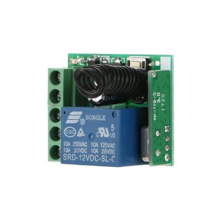
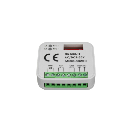
Remote Control Radio Receiver
Ship or pick up from our office.
Remote Control Radio Receiver
- NC/NO Output
- Easy to program new remotes
- The remote control button is covered to prevent accidental pressing.
- This radio receiver can be added to almost all the gate operators such as Italian, Chinese, swing gate operators, sliding gate operators, and overhead garage doors.
- Compatible with 100 remotes.
- Small case and easy to install
- The wireless RF signals can pass through walls, floors, doors, or windows. You can use two or more units in the same place.
A gate opener's remote control radio receiver is a device that receives radio signals from a handheld remote control, triggering the gate opener's motor to open or close the gate.
Here's a more detailed explanation:
-
Receives Signals:The receiver picks up radio waves transmitted by the remote control.
-
Decodes Commands:It interprets the specific signal pattern to understand the desired action (e.g., open, close, stop).
-
Controls Devices:The receiver then sends signals to the gate opener's motor, causing it to move the gate accordingly.
-
Part of a System:It's a crucial component of the remote control system, working with the transmitter (remote) to enable wireless control of the gate.
-
Frequency:Gate opener receivers typically operate on frequencies like 433 MHz or 315 MHz.
-
Installation:The receiver is usually wired to the gate operator's control board and may require programming to associate it with specific remote controls.


