Shop
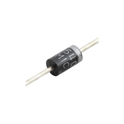
Diode 1N5408
Ship or pick up from our office.
Diode 1N5408
The 1N5408 is a common general-purpose rectifier diode. It's designed to allow electric current to flow primarily in one direction, making it crucial for converting alternating current (AC) to direct current (DC). Think of it like a one-way valve for electricity. It belongs to the 1N540x series of power diodes, known for their ability to handle relatively high current and voltage. Here are its key characteristics and common uses: Key Features- High Reverse Voltage Rating: It can withstand a maximum repetitive reverse voltage () of 1000V. This means it can block high voltages when current tries to flow in the "wrong" direction.
- High Forward Current Capacity: It's rated for an average rectified forward current () of 3 Amperes (A). This indicates it can handle a significant amount of current flowing through it in the correct direction.
- High Surge Current Capability: The 1N5408 can handle non-repetitive peak forward surge currents () of up to 200A for short durations, protecting circuits from sudden power spikes.
- Low Forward Voltage Drop: When conducting, it has a relatively low forward voltage drop () of approximately 1.0V to 1.2V at its rated current. A lower voltage drop means less power is lost as heat.
- Standard Recovery: It's a "standard recovery" diode, meaning its switching speed is relatively slow compared to fast recovery diodes. This makes it suitable for power rectification at lower frequencies (like 50/60 Hz AC).
- DO-201 Package: It typically comes in a DO-201 axial-leaded package, which is a through-hole component with leads extending from both ends, allowing for easy mounting on circuit boards.
- Wide Operating Temperature Range: It can operate and be stored in a wide temperature range, typically from -65°C to +175°C.
- Power Supplies and Rectifiers: This is its primary application. It efficiently converts AC input voltage into pulsating DC, which can then be smoothed by capacitors to provide a stable DC output for electronic devices. This includes full-wave and half-wave rectifier circuits.
- Battery Chargers: Used to convert AC wall power into DC for charging batteries.
- Voltage Regulation Circuits: Helps in maintaining a stable output voltage by rectifying current.
- Protection Circuits: Its ability to block reverse current makes it useful for reverse polarity protection, preventing damage to sensitive components if the power supply is connected incorrectly.
- Freewheeling Diode: Used in inductive circuits (like those with relays or motors) to provide a path for stored energy to dissipate when the current is switched off, preventing voltage spikes that could damage other components.
- Voltage Doubler Circuits: Can be used in circuits designed to effectively double the input voltage.
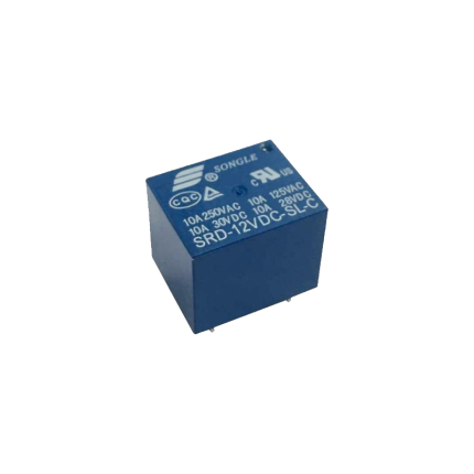
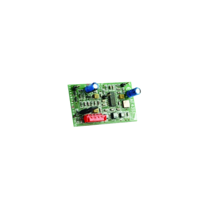
Relay Mini PCB 5-Pin 10A
Ship or pick up from our office.
Relay Mini PCB 5-Pin 10A
A Relay Mini PCB 5-Pin 10A is a compact, electromechanical switch designed to be mounted directly onto a printed circuit board (PCB). It uses a small control voltage to switch a larger current, making it useful for isolating control circuits from power circuits or for switching higher-power loads with a low-power signal. Key Features and Specifications- Mini: This indicates its small physical size, making it suitable for applications where space is limited.
- PCB: This means it's designed for Printed Circuit Board mounting. Its pins are typically configured to be soldered directly into holes on the PCB.
- 5-Pin: These five pins usually consist of:
- Two pins for the coil: These are where the control voltage is applied to energize the coil and activate the relay.
- Three pins for the contacts: These typically include a common (COM) pin, a normally open (NO) pin, and a normally closed (NC) pin.
- 10A: This is the maximum current rating that the relay's contacts can safely switch. It means the relay is capable of handling up to 10 amperes of current through its switched contacts.
- Normally Open (NO): The contact is open when the coil is de-energized and closes when the coil is energized.
- Normally Closed (NC): The contact is closed when the coil is de-energized and opens when the coil is energized.
- Automotive applications: For controlling lights, motors, and other accessories.
- Home automation: Switching lights, appliances, and HVAC systems.
- Industrial control: In PLCs (Programmable Logic Controllers) and other control panels.
- Appliance control: In washing machines, refrigerators, and microwave ovens.
- DIY electronics projects: Where low-power signals need to control higher-power devices.
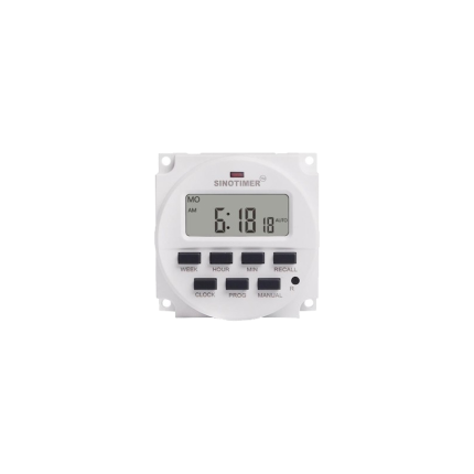
Digital programmable ON/OFF relay
Ship or pick up from our office.
Digital programmable ON/OFF relay
A digital programmable ON/OFF relay is an electronic switch that can be programmed to turn electrical devices on or off at specific times or intervals. It combines the fundamental switching functionality of a traditional relay with the advanced timing and control capabilities of a digital timer or microcontroller. This allows for automated control of various devices and systems without constant human intervention. How it Works At its core, a digital programmable ON/OFF relay operates similarly to a standard relay by using a small electrical current to control a larger electrical circuit. However, the "digital programmable" aspect introduces a sophisticated timing mechanism.- Digital Interface: Unlike mechanical or analog timer relays with physical dials, digital programmable relays feature an LED or LCD display and a keypad or buttons for programming. This allows users to set precise ON/OFF times, durations, and sequences.
- Microcontroller-Based: Most digital programmable relays use a microcontroller to manage the timing and control logic. This internal "brain" keeps track of time and executes the programmed instructions.
- Timing Functions: These relays offer a wide range of timing functions, including:
- On-delay: The relay turns on after a preset delay once activated.
- Off-delay: The relay turns off after a preset delay once deactivated.
- Interval timing: The relay stays on for a specific duration after activation.
- Cyclic operation: The relay repeatedly cycles ON and OFF at set intervals.
- Astronomic timing: Some advanced models can turn devices on/off based on sunrise and sunset times by calculating the solar position.
- Photocell integration: Others may include light sensors to activate based on ambient light levels.
- Memory Retention: Many programmable relays can store settings in memory even after a power interruption, ensuring that the programmed schedule is not lost.
- Programmable Timing: Offers precise control over when devices turn on and off.
- Automation: Reduces the need for manual operation, leading to increased efficiency.
- Energy Savings: Allows for optimization of energy usage by ensuring devices are only active when needed.
- Flexibility and Versatility: Can be configured for a wide array of applications due to various timing modes.
- Compact Design: Often more compact than systems using multiple hardwired timers and relays.
- Ease of Use: User-friendly interfaces for setting up programs.
- Reliability: Many are solid-state, meaning they have no moving parts, which increases durability and reduces noise compared to electromechanical relays.
- Home Automation: Controlling lighting, appliances, or other devices based on a preset schedule (e.g., security lights, garden irrigation).
- Industrial Automation: Managing machinery, conveyors, pumps, motors, and other equipment in factories or manufacturing facilities.
- Building Management Systems: Automated control of HVAC systems (heating, ventilation, air conditioning), lighting (e.g., streetlights turning on at dusk), and security systems.
- Commercial Applications: Used in vending machines, amusement equipment, and commercial appliances.
- Agriculture: Controlling irrigation pumps or greenhouse lighting.
- Security Systems: Activating alarms or security lights at specific times or in response to sensors.
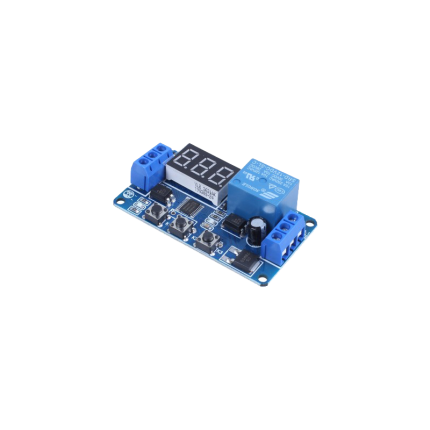
Programmable timer relay
Ship or pick up from our office.
Programmable timer relay
A programmable timer relay is an electronic device that combines the functions of a timer and a relay, allowing users to set specific time delays for switching electrical circuits on or off. Essentially, it acts as an automated switch that operates based on pre-programmed time intervals. This enables the automation of various processes and equipment across a wide range of applications. How it Works Programmable timer relays incorporate internal circuitry (often microcontrollers or digital logic chips) that allow for precise timekeeping and control. Here's a general overview of how they function:- Control Signal: The programmable timer relay receives an input or "trigger" signal, which initiates the timing process. This signal can come from a switch, sensor, or another control device.
- Timing Mechanism: Once the signal is received, the internal timing mechanism begins to count down or up based on the programmed parameters.
- Delay Period: During this delay, the relay's contacts remain in their initial state (either normally open or normally closed).
- Contact Switching: Once the programmed delay period elapses, the relay's contacts change state, either closing to allow current to flow or opening to interrupt it.
- Maintaining State & Resetting: The relay maintains its new state until the input signal is removed, or a reset function is triggered. Programmable relays offer various timing modes, such as:
- On-delay: The relay activates after a set delay once the input signal is applied.
- Off-delay: The relay deactivates after a set delay once the input signal is removed.
- Interval: The relay activates for a set period and then deactivates.
- Cyclic: The relay repeatedly alternates between on and off states for specified durations.
- Industrial Automation: They control the sequencing of machinery, conveyor belts, pumps, and other equipment in manufacturing processes, ensuring precise timing and preventing system overloads.
- Lighting Control: Used in homes, commercial buildings, and street lighting to turn lights on and off at specific times or based on ambient light levels, optimizing energy consumption and security.
- HVAC Systems: Regulate fan operations, compressor cycles, and defrost cycles in heating, ventilation, and air conditioning systems to maintain desired temperatures and reduce energy use.
- Security Systems: Implement delays for door locks, alarm systems, and surveillance cameras, allowing for controlled access and scheduled activation/deactivation.
- Pump Control: Manage water pumps, sewage pumps, and sump pumps, ensuring they operate only when needed, which conserves water and prevents pump damage.
- Home Automation: Automate various household appliances like irrigation systems, washing machines, and dishwashers.
- Vehicle Systems: Control functions like intermittent windshield wipers and turn signals.
- Versatility and Customization: They can be programmed for various timing functions and sequences within a single unit, offering great flexibility for diverse applications.
- Energy Savings: By automating on/off cycles and ensuring equipment runs only when necessary, they help reduce energy consumption and costs.
- Increased Efficiency: They enable automated control of equipment and processes, improving overall operational efficiency and reducing the need for manual intervention.
- Reduced Components and Wiring: By integrating multiple timing and switching functions into one device, they can replace several individual timers and relays, simplifying wiring, reducing component inventory, and saving space in control panels.
- Cost-Effectiveness: For simpler automation tasks, they offer a more economical solution compared to full-fledged PLCs.
- Ease of Use: Many programmable timer relays feature user-friendly digital interfaces or software, making them relatively easy to configure without requiring extensive programming knowledge.
- Precise Time Control: They offer high temporal precision, with delays ranging from milliseconds to several hours.
- Troubleshooting: Integrated displays often provide alarm messages and I/O status, simplifying troubleshooting.
Delay relay 0.5 Sec – AC 24 V to DC 12 V
Ship or pick up from our office.
Delay relay 0.5 Sec - AC 24 V to DC 12 V
A "delay relay 0.5 Sec - AC 24 V to DC 24 V" is a time delay relay that is designed to:- Operate with a control voltage of 24 volts, which can be either Alternating Current (AC) or Direct Current (DC). This dual compatibility (AC/DC 24V) is a key feature, as many relays are specific to one type of current.
- Introduce a delay of 0.5 seconds before its contacts change state. This delay can be an "on-delay" (contacts close/open after 0.5 seconds when power is applied) or an "off-delay" (contacts remain closed/open for 0.5 seconds after power is removed), or other timing functions depending on the specific relay's design.
- Switch or control a separate circuit, which may be a 24V DC circuit. The "AC 24V to DC 24V" in the description refers to the relay's input power compatibility (it can be powered by either 24V AC or 24V DC) and its output capability (it's often used to control 24V DC loads). It is not a direct AC to DC converter for the load it's switching, but rather indicates its flexible control voltage. The relay itself doesn't convert the power; it merely switches it on or off after a delay. If the controlled circuit specifically requires DC, the relay's contacts would simply switch the 24V DC power to that circuit.
- Prevent false triggering: A brief fluctuation in voltage or a momentary signal might cause immediate activation in a standard relay. A short delay (like 0.5 seconds) can prevent such nuisance activations.
- Create timed sequences: In automated processes, certain steps may need to occur in a specific order with set delays in between. For example, a delay relay could ensure one motor starts before another or that a safety purge cycle completes before a furnace ignites.
- Control motor starts/stops: They can be used for "soft starting" motors, gradually increasing voltage to reduce inrush current, or for ensuring a motor has fully stopped before another action begins.
- HVAC systems: They prevent "short cycling" of compressors, which can damage the unit, by introducing a delay between successive starts.
- Lighting control: Ensuring lights stay on for a set period after activation (e.g., in stairwells) or controlling emergency lighting.
- Security systems: Providing a brief delay before an alarm triggers, allowing authorized personnel to disarm the system.
- On-delay (Delay on Make): The most common type. The contacts change state only after the set time delay has elapsed after the control voltage is applied.
- Off-delay (Delay on Break): The contacts change state immediately when the control voltage is applied, but only return to their original state after the set time delay has elapsed after the control voltage is removed.
- Interval: The contacts change state immediately when the control voltage is applied, and then return to their original state after the set time delay.
- Repeat Cycle: The relay continuously cycles between on and off states with specific time delays as long as the control voltage is applied.
Delay relay 0.5 Sec – AC 24 V to AC 24 V
Ship or pick up from our office.
Delay relay 0.5 Sec - AC 24 V to AC 24 V
delay relay 0.5 Sec - AC 24 V to AC 24 V is a type of electrical relay that introduces a 0.5-second time delay in a circuit, specifically designed to operate with a 24-volt AC (Alternating Current) power supply. This means that when the control voltage (24V AC) is applied or removed, the relay's output contacts won't change their state immediately; instead, there will be a half-second pause before they do. Here's a breakdown of what each part of the description means:- Delay Relay (or Time Delay Relay/Timer Relay): This is a control device that, unlike a standard relay, incorporates a timing function. It's used to control an event based on a pre-selected time interval.
- 0.5 Sec: This specifies the duration of the time delay. In this case, it's a very short half-second delay. Time delays can range from milliseconds to hours or even days, depending on the relay.
- AC 24 V (Input/Control Voltage): This indicates the type and voltage of the power supply required to energize the relay's coil or internal control circuitry. "AC" means Alternating Current, and "24 V" is the nominal voltage.
- to AC 24 V (Output/Load Voltage): While not explicitly stated as "output," this implies that the relay is likely intended to switch a 24V AC load. This means the contacts within the relay are rated to handle 24V AC to control another part of the circuit or a device. It's important to note that the load voltage can sometimes be different from the control voltage, but in this specific phrasing, it suggests both are 24V AC.
- On-Delay (Normally-Open, Timed-Closed - NOTC): The most common type. When the control voltage is applied, the timing period begins. After 0.5 seconds, the output contacts close. The contacts remain closed as long as the control voltage is present.
- Off-Delay (Normally-Open, Timed-Open - NOTO): When the control voltage is applied, the output contacts close immediately. When the control voltage is removed, the 0.5-second delay begins. After this delay, the contacts open.
- One-Shot: Provides a single output pulse of a specified duration (in this case, 0.5 seconds) when triggered.
- Repeat Cycle: Alternates between ON and OFF states for defined durations, creating a repeating cycle. This particular relay with a fixed 0.5-second delay is less likely to be a multi-function repeat cycle unless it's just one setting within a programmable unit.
- Sequencing Operations: Ensuring one component starts or stops slightly after another in a controlled sequence.
- Motor Control: Providing a brief delay before starting a motor (e.g., for pre-lubrication pumps to stabilize).
- Safety Interlocks: Implementing a short delay to ensure certain conditions are met before an action can occur.
- HVAC Systems: Timing the activation or deactivation of fans, compressors, or other components.
- Conveyor Systems: Coordinating the starting or stopping of multiple conveyor belts to prevent material jams.
- Lighting Control: For example, a short delay before turning on a light in a specific area
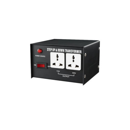
Power inverter 110 V to 220 V
Ship or pick up from our office.
Power inverter 110 V to 220 V
A power inverter 110V to 220V (also known as a step-up voltage converter) is an electronic device that transforms an input voltage of 110 volts (V) into an output voltage of 220V. This type of inverter is crucial for bridging the gap between different regional electrical standards. How It Works At its core, a 110V to 220V power inverter utilizes a transformer to achieve the voltage conversion. Here's a simplified explanation:- Input (DC to AC Conversion for Inverters): While the prompt asks about a "power inverter 110V to 220V," it's important to clarify that traditional inverters convert DC (Direct Current) from a battery (e.g., 12V, 24V, 48V) into AC (Alternating Current). If the input is already 110V AC, then the device is more accurately called a voltage converter or transformer, as it's stepping up AC to AC. However, some inverters are designed to take a DC input and produce 110V AC or 220V AC, or even both.
- Step-Up Transformation: For a 110V AC to 220V AC conversion, the device contains a transformer with primary and secondary coils. The 110V AC from the power source is fed into the primary coil. Through electromagnetic induction, this voltage is "stepped up" to 220V in the secondary coil, which then becomes the output.
- Waveform: Inverters and converters can produce different types of AC waveforms:
- Pure Sine Wave: This is the most desirable waveform, replicating the smooth, consistent power from a utility grid. It's ideal for sensitive electronics.
- Modified Sine Wave: This is a cruder approximation of a sine wave and is generally suitable for less sensitive appliances, but can cause issues or damage with certain delicate electronics.
- Power Capacity (Wattage): This indicates how much power the device can supply. Ensure it's sufficient to handle the total wattage of the appliances you intend to connect. Exceeding the inverter's capacity can lead to damage.
- Efficiency: A higher efficiency rating means less energy is wasted as heat during the conversion process, which is important for battery-powered setups.
- Safety Features: Look for features like overload protection, short-circuit protection, and surge protection to safeguard your appliances and the inverter itself.
- Frequency: Electrical grids operate at either 50 Hz or 60 Hz. Ensure the inverter's output frequency matches the requirements of your appliances. Some inverters can switch between frequencies.
- Portability: Some are designed for travel, while others are larger for industrial or home use.
- International Travel: They allow travelers from countries with 110V systems (like North America) to use their 220V appliances (like hair dryers, chargers) in countries with 220V outlets (common in Europe, Asia, and other regions).
- Using Imported Appliances: If you have an appliance designed for 220V (e.g., a European kitchen appliance) but your home has 110V outlets, a step-up converter enables you to use it.
- Industrial and Specialized Applications: In industries, they can be used for automation and control systems, telecommunications, and emergency power systems to ensure compatible power supply for various equipment.
- Renewable Energy Systems: In off-grid solar or wind power setups, inverters convert DC power from batteries into the required AC voltage (which could be 110V or 220V depending on the load).
- High-Power Appliances: Some larger appliances or specialized tools might require 220V power, even in regions where 110V is standard for most household items. A converter can provide the necessary voltage without extensive electrical rewiring.
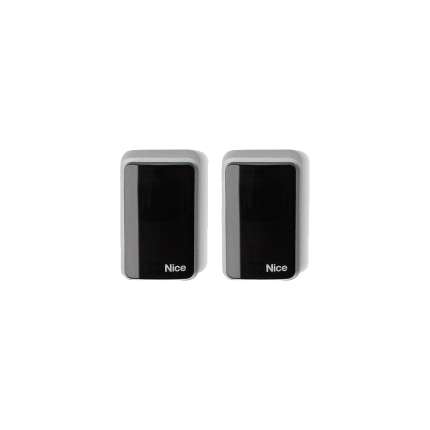
Safety sensor – Nice Era-EPM
Ship or pick up from our office.
Safety sensor - Nice Era-EPM
The Nice Era-EPM is a photoelectric safety sensor commonly used in automation systems for gates, garage doors, barriers, and similar installations. It's also often referred to as a photocell or beam sensor. Here's a breakdown of what it is and its key features: Purpose: Its primary function is to enhance safety by detecting obstacles in the path of a moving gate or door. It consists of a transmitter (TX) and a receiver (RX) that are installed facing each other. The transmitter emits an infrared beam, and if this beam is interrupted by an object, the receiver signals the control unit to stop or reverse the automation system, preventing accidents, injuries, or damage to vehicles. Key Features and Specifications:- Photoelectric Technology: It uses an infrared beam to detect obstructions.
- Transmitter (TX) and Receiver (RX): Comes as a pair, with one unit transmitting the beam and the other receiving it.
- Relay Output: It's a relay photocell, meaning it sends a signal to the control unit via a relay output.
- Range: Typically has a useful range of 15 meters, which can be extended up to 30 meters in some configurations (e.g., by cutting a "+10m" electrical bridge). However, range can be reduced in adverse weather conditions like fog, rain, or dust.
- Anti-Glare Circuitry: Designed with an anti-glare circuit to minimize interference from sunlight, ensuring reliable performance in various lighting conditions.
- Durable Construction: Features an ABS body that is resistant to weather conditions, making it suitable for outdoor use (IP44 protection rating).
- Easy Installation: Known for its simplified assembly and installation procedure. Some versions (like those with Nice BlueBUS technology) require only two wires for connection to compatible control units, simplifying wiring.
- Wide Angle of Reception: Generally has a 10° (or 8° with a reduction cone) angle of reception, which helps in compensating for minor alignment issues.
- Compatibility: While it's a Nice-branded product, it's often described as a "universal photocell" compatible with most gate and garage door automation systems, especially those that accept standard relay inputs. Some models also feature Nice BlueBUS technology for seamless integration with Nice control units that support it.
- Safety Compliance: It is a Type D presence detector according to EN 12453 standard, which means it detects obstacles on the optical axis. When connected to a control unit with a "phototest" function, it can achieve Category 2 safety against malfunctions according to EN 954-1.
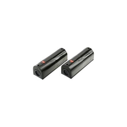
Safety sensor – BFT FL130
Ship or pick up from our office.
Safety sensor - BFT FL130
The BFT FL130 is a photoelectric safety sensor designed primarily for use with automated gates and doors. It's a crucial safety component that prevents the gate or door from closing if an obstacle, such as a person or vehicle, is detected in its path. Here's a breakdown of its key aspects: How it Works The BFT FL130 operates as a pair of photocells, consisting of a transmitter (TX) and a receiver (RX). These units are typically mounted on opposite sides of the gate or door opening. The transmitter emits an infrared beam towards the receiver. If anything breaks this beam (e.g., a person walking through, a car passing), the receiver detects the interruption and sends a signal to the gate's control unit. This signal then triggers a safety mechanism, causing the gate to stop its movement or reverse direction to avoid impact. Features and Specifications- Type: Photoelectric safety sensor (photocell).
- Components: Transmitter and receiver pair.
- Function: Detects obstacles in the path of automated gates and doors to prevent accidents.
- Detection Method: Infrared beam.
- Applications: Commonly used in residential and commercial settings for automated swing gates, sliding gates, and garage doors.
- Max Range: Up to 30 meters (can be reduced by 50% in adverse weather conditions like fog or heavy rain).
- Power Supply: Typically 20-31 VAC or 22-30 VDC.
- Absorption: Approximately 70mA per pair.
- Relay Contacts: 1A at 24 VAC-DC.
- Working Temperature: Generally from -15°C to +70°C (some sources say -5°C to +70°C).
- Protection Rating: IP54, meaning it's protected against dust ingress and splashing water.
- Mounting: Should be aligned and mounted at a height between 40 and 60 cm from the ground on flat, parallel surfaces.
- Dimensions: Compact, typically around 115mm x 32mm x 26mm.
- Versions: There is also a BFT FL130B version, which may offer additional features like self-alignment and is designed to meet EN12453 regulations for Type D safety devices when connected to a compatible control unit that verifies safety device functionality.


Pedestrian gate manual lock (One side key)
Ship or pick up from our office.
Pedestrian gate manual lock (One side key)
A "pedestrian gate manual lock (one side key)" refers to a type of locking mechanism for a gate that is operated manually and requires a key to unlock it from one side, while the other side allows for easy exit without a key. Here's a breakdown of its key features:- Manual Operation: This lock doesn't rely on electricity or automation. You physically use your hand to engage or disengage the locking mechanism.
- One-Sided Key Access: The defining characteristic is that a physical key is needed to unlock the gate from one specific side (usually the exterior or entry side).
- Easy Exit (Thumb-Turn, Latch, or Push Pad): On the interior or exit side, there's typically a simple mechanism like a thumb-turn, lever, push pad, or a basic latch that allows for quick and easy opening without needing a key. This is often a safety feature, especially for emergency exits.
- Security: It provides a basic level of security, preventing unauthorized entry from the keyed side.
- Power Independence: Since it's manual, it's not affected by power outages.
- Common Use Cases: These locks are frequently found on garden gates, backyard gates, pool gates, and other pedestrian access points where controlled entry is desired but a quick exit is also necessary.

Doorbell SDB111
Ship or pick up from our office.
Doorbell SDB111
The "Doorbell SDB111" primarily refers to a wired doorbell system that operates on a 12-volt DC power supply. It's often associated with Royal Electronics Technology Center Co. and is commonly used for security access control in homes, offices, and other buildings. Here's a breakdown of its typical characteristics about the doorbell SDB111:- Wired System: The "12V" in its name signifies that it's a wired doorbell, meaning it connects to a power source via electrical wires. This usually involves a transformer that converts household voltage to 12V DC.
- Low Voltage: Like many doorbell systems, it operates on low voltage for safety.
- Functionality: Its primary function is to produce a chime sound (like a "ding-dong") when the doorbell button is pressed. It's often chosen for its durability and continuous function without needing battery replacements.
- Installation: These doorbells can be installed with screws or double-sided adhesive tape and typically come with wiring diagrams.
- Security Integration: They are considered a good security measure as they are external and can be integrated with other security systems.
- Access Control: The SDB111 is specifically mentioned in the context of access control systems, suggesting its use in managing entry to a property.
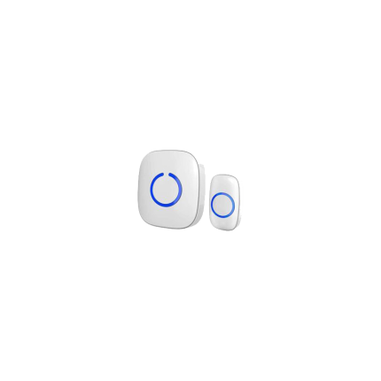
Wireless Doorbell
Ship or pick up from our office.
Wireless Doorbell
A wireless doorbell is a modern type of doorbell that operates without the need for physical wiring between the outdoor button and the indoor chime unit. Unlike traditional wired doorbells that rely on an electrical circuit, wireless doorbells use radio waves (or sometimes Wi-Fi or Bluetooth) to transmit a signal when the button is pressed. Here's a breakdown of its key components and how it works:- Transmitter (Doorbell Button): This is the part located outside your door that a visitor presses. It typically contains a small battery (though some "kinetic energy" versions generate power from the press itself) and sends a wireless signal when activated.
- Receiver (Chime Unit): This is the indoor component that produces the sound (chime or melody) when it receives the signal from the transmitter. Receivers can be battery-operated for portability or plug into a standard electrical outlet.
- When a visitor presses the doorbell button (transmitter), it sends a unique radio frequency (RF) signal.
- The signal travels wirelessly through the air.
- The receiver inside your home detects this signal.
- Upon receiving the signal, the receiver activates its chime or melody, alerting you to the visitor.
- Easy Installation: No need for complex wiring, drilling holes, or hiring an electrician. This makes them ideal for renters or anyone looking for a quick and simple setup.
- Flexibility and Portability: Since there are no wires, you can place the chime unit virtually anywhere in your home, and even move it around if needed. Many systems also allow for multiple receivers throughout a large house or property.
- Customization: Most wireless doorbells offer a variety of chime melodies and adjustable volume levels, allowing you to personalize the sound.
- Advanced Features (Smart Doorbells): Many modern wireless doorbells, often called "smart doorbells," integrate with Wi-Fi and offer additional features like:
- Video cameras: Allowing you to see who's at your door from your smartphone, even when you're not home.
- Two-way audio: Enabling you to speak with visitors remotely.
- Motion detection: Alerting you to activity outside your door.
- Smartphone notifications: Sending alerts to your phone when someone rings the bell or motion is detected.
- Integration with smart home systems: Connecting with other devices like smart lights or security systems.
- Enhanced Security: With features like video recording and remote monitoring, wireless doorbells can deter potential intruders and provide valuable evidence in case of an incident.


