Shop
Relay 5-Pin 40A
Ship or pick up from our office.
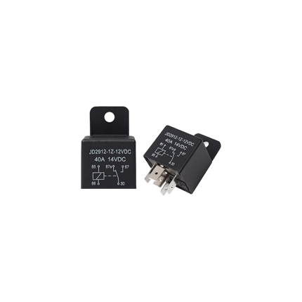
Relay 5-Pin 40A
A 5-pin 40A relay is an electromechanical switch commonly used in automotive and other applications. It allows a low-power electrical signal to control a higher-power circuit. The "5-pin" refers to the number of terminals it has, and "40A" indicates that its contacts can safely handle a maximum current of 40 amps. How it Works A relay essentially functions like a remote-controlled switch. It has two main circuits:- Control Circuit (Coil): This low-power circuit energizes an electromagnet inside the relay.
- Switched Circuit (Contacts): This high-power circuit is controlled by the electromagnet, either opening or closing connections to a device.
- Pins 85 and 86: These are the coil terminals. When a small current (typically 12V DC in automotive applications) is applied across these pins, it creates a magnetic field.
- Pin 30: This is the common terminal for the switched circuit. It's usually connected to the main power source (e.g., battery) through a fuse.
- Pin 87: This is the Normally Open (NO) contact. When the relay coil is energized, pin 30 connects to pin 87, allowing current to flow to the connected device.
- Pin 87a: This is the Normally Closed (NC) contact. When the relay coil is not energized, pin 30 is connected to pin 87a. When the coil is energized, this connection breaks.
- High-Current Control: They allow you to control high-current devices (like headlights, fuel pumps, or cooling fans) with a low-current switch. This protects the sensitive, smaller switches from being damaged by excessive current.
- Reduced Voltage Drop: By placing the relay closer to the high-current device and power source, you can use shorter runs of heavier gauge wire for the high-current circuit, minimizing voltage drop and ensuring the device receives adequate power.
- Safety: They isolate high-current circuits from the passenger compartment, enhancing safety.
- Automotive: Headlights, fog lights, horns, fuel pumps, electric cooling fans, power windows, central locking, and various aftermarket accessories.
- Industrial Control: Switching motors, solenoids, and other heavy-duty equipment.
- General Purpose: Any application where a low-power signal needs to control a higher-power circuit.
- Pin 85: Connect to ground (-).
- Pin 86: Connect to the positive (+) side of your control switch. When this switch is activated, it provides power to the coil.
- Pin 30: Connect directly to the positive (+) terminal of your battery, always through an appropriately sized fuse.
- Pin 87: Connect to the positive (+) terminal of the device you want to power when the relay is activated (Normally Open connection).
- Pin 87a: (Optional) Connect to a device you want to power when the relay is not activated (Normally Closed connection).
Relay Mini PCB 5-Pin 10A
Ship or pick up from our office.
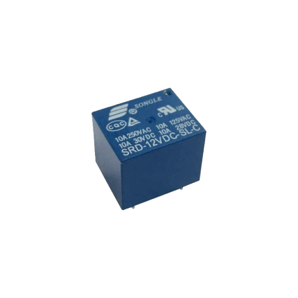
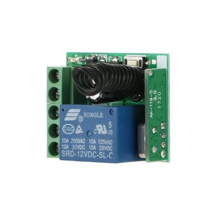
Relay Mini PCB 5-Pin 10A
A Relay Mini PCB 5-Pin 10A is a compact, electromechanical switch designed to be mounted directly onto a printed circuit board (PCB). It uses a small control voltage to switch a larger current, making it useful for isolating control circuits from power circuits or for switching higher-power loads with a low-power signal. Key Features and Specifications- Mini: This indicates its small physical size, making it suitable for applications where space is limited.
- PCB: This means it's designed for Printed Circuit Board mounting. Its pins are typically configured to be soldered directly into holes on the PCB.
- 5-Pin: These five pins usually consist of:
- Two pins for the coil: These are where the control voltage is applied to energize the coil and activate the relay.
- Three pins for the contacts: These typically include a common (COM) pin, a normally open (NO) pin, and a normally closed (NC) pin.
- 10A: This is the maximum current rating that the relay's contacts can safely switch. It means the relay is capable of handling up to 10 amperes of current through its switched contacts.
- Normally Open (NO): The contact is open when the coil is de-energized and closes when the coil is energized.
- Normally Closed (NC): The contact is closed when the coil is de-energized and opens when the coil is energized.
- Automotive applications: For controlling lights, motors, and other accessories.
- Home automation: Switching lights, appliances, and HVAC systems.
- Industrial control: In PLCs (Programmable Logic Controllers) and other control panels.
- Appliance control: In washing machines, refrigerators, and microwave ovens.
- DIY electronics projects: Where low-power signals need to control higher-power devices.
Relay Mini PCB 8-Pin 1A
Ship or pick up from our office.
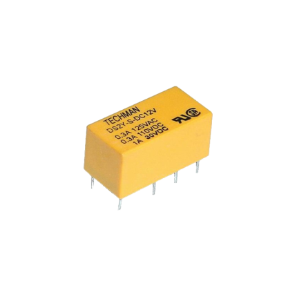
Relay Mini PCB 8-Pin 1A
A Relay Mini PCB 8-Pin 1A is a small, electronic switch designed to be mounted directly onto a Printed Circuit Board (PCB). It has eight pins for connections and its contacts can safely switch a maximum current of 1 Ampere (1A). Key Characteristics- Miniature Size: The "Mini" in its name indicates its compact dimensions, making it suitable for circuits where space is limited.
- PCB Mountable: It's designed for through-hole soldering onto a PCB, integrating seamlessly into electronic designs.
- 8-Pin Configuration: These pins serve various purposes, including connecting the coil (which activates the relay) and the switch contacts (which control the electrical load).
- 1A Current Rating: This is the maximum current that can safely flow through the relay's contacts when they are closed.
- Coil Voltage: The relay's coil operates on a specific DC voltage (e.g., 3V, 5V, 12V, 24V). Applying this voltage to the coil creates a magnetic field that mechanically opens or closes the contacts.
- Contact Configuration: Many 8-pin mini PCB relays are DPDT (Double Pole, Double Throw), meaning they have two sets of contacts, each with both normally open (NO) and normally closed (NC) positions. This allows for versatile switching operations.
- Isolation: Relays provide electrical isolation between the control circuit (coil) and the load circuit (contacts), enhancing safety and preventing interference.
- Remote Control Systems: Used to switch power to devices based on signals from a remote.
- Communication Equipment: For routing or switching signals in telecommunications and data networks.
- Automatic Control Systems: In automation processes to control motors, lights, or other actuators.
- Household Appliances: Found in various home electronics to manage power to different components.
- Automotive Systems: Employed in vehicles to control functions like lights, locks, and windows.
- Instrumentation and Measurement Devices: For precise signal routing and control in sensitive equipment.
Remote Control Radio Receiver
Ship or pick up from our office.
Remote Control Radio Receiver
- NC/NO Output
- Easy to program new remotes
- The remote control button is covered to prevent accidental pressing.
- This radio receiver can be added to almost all the gate operators such as Italian, Chinese, swing gate operators, sliding gate operators, and overhead garage doors.
- Compatible with 100 remotes.
- Small case and easy to install
- The wireless RF signals can pass through walls, floors, doors, or windows. You can use two or more units in the same place.
A gate opener's remote control radio receiver is a device that receives radio signals from a handheld remote control, triggering the gate opener's motor to open or close the gate.
Here's a more detailed explanation:
-
Receives Signals:The receiver picks up radio waves transmitted by the remote control.
-
Decodes Commands:It interprets the specific signal pattern to understand the desired action (e.g., open, close, stop).
-
Controls Devices:The receiver then sends signals to the gate opener's motor, causing it to move the gate accordingly.
-
Part of a System:It's a crucial component of the remote control system, working with the transmitter (remote) to enable wireless control of the gate.
-
Frequency:Gate opener receivers typically operate on frequencies like 433 MHz or 315 MHz.
-
Installation:The receiver is usually wired to the gate operator's control board and may require programming to associate it with specific remote controls.
Remote starter immobilizer bypass module
Ship or pick up from our office.
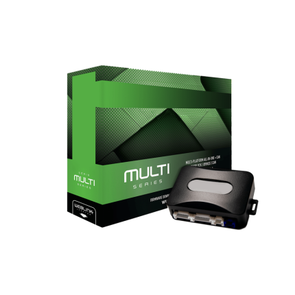
Remote starter immobilizer bypass module
A remote starter immobilizer bypass module is an essential component when installing an aftermarket remote car starter in most modern vehicles. Its sole purpose is to "trick" the vehicle's factory immobilizer system into believing that the correct key is present in the ignition, allowing the engine to start remotely. Here's a breakdown of what that means: What is a remote starter immobilizer bypass module system? Since around the late 1990s, and mandated for all new cars sold in Canada since the year 2000, virtually every vehicle is equipped with an electronic immobilizer system as an anti-theft measure. This system prevents the engine from starting unless it detects a specific, valid code.- How it works:
- Your car key (or smart key fob) contains a small electronic chip called a transponder. This chip stores a unique electronic code.
- When you insert the key into the ignition (or, with push-button start, have the fob within range), the vehicle's onboard computer (often via an antenna coil around the ignition barrel) reads the code from the transponder.
- If the code matches what's stored in the vehicle's ECU (Engine Control Unit), the remote starter immobilizer bypass module is deactivated, and the engine is allowed to start and run.
- If the code doesn't match, or if no valid code is detected (e.g., someone tries to hot-wire the car, or uses an unprogrammed key), the immobilizer will prevent the engine from starting, or it will start for a few seconds and then immediately shut off. It typically disables vital functions like the fuel pump or ignition system.

RFID Card Access Control

RFID Tag Access Control
Safety sensor – BFT FL130
Ship or pick up from our office.
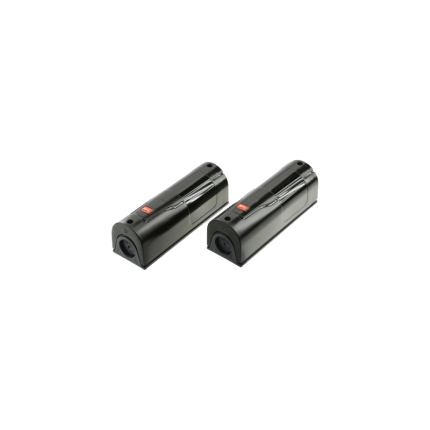
Safety sensor - BFT FL130
The BFT FL130 is a photoelectric safety sensor designed primarily for use with automated gates and doors. It's a crucial safety component that prevents the gate or door from closing if an obstacle, such as a person or vehicle, is detected in its path. Here's a breakdown of its key aspects: How it Works The BFT FL130 operates as a pair of photocells, consisting of a transmitter (TX) and a receiver (RX). These units are typically mounted on opposite sides of the gate or door opening. The transmitter emits an infrared beam towards the receiver. If anything breaks this beam (e.g., a person walking through, a car passing), the receiver detects the interruption and sends a signal to the gate's control unit. This signal then triggers a safety mechanism, causing the gate to stop its movement or reverse direction to avoid impact. Features and Specifications- Type: Photoelectric safety sensor (photocell).
- Components: Transmitter and receiver pair.
- Function: Detects obstacles in the path of automated gates and doors to prevent accidents.
- Detection Method: Infrared beam.
- Applications: Commonly used in residential and commercial settings for automated swing gates, sliding gates, and garage doors.
- Max Range: Up to 30 meters (can be reduced by 50% in adverse weather conditions like fog or heavy rain).
- Power Supply: Typically 20-31 VAC or 22-30 VDC.
- Absorption: Approximately 70mA per pair.
- Relay Contacts: 1A at 24 VAC-DC.
- Working Temperature: Generally from -15°C to +70°C (some sources say -5°C to +70°C).
- Protection Rating: IP54, meaning it's protected against dust ingress and splashing water.
- Mounting: Should be aligned and mounted at a height between 40 and 60 cm from the ground on flat, parallel surfaces.
- Dimensions: Compact, typically around 115mm x 32mm x 26mm.
- Versions: There is also a BFT FL130B version, which may offer additional features like self-alignment and is designed to meet EN12453 regulations for Type D safety devices when connected to a compatible control unit that verifies safety device functionality.
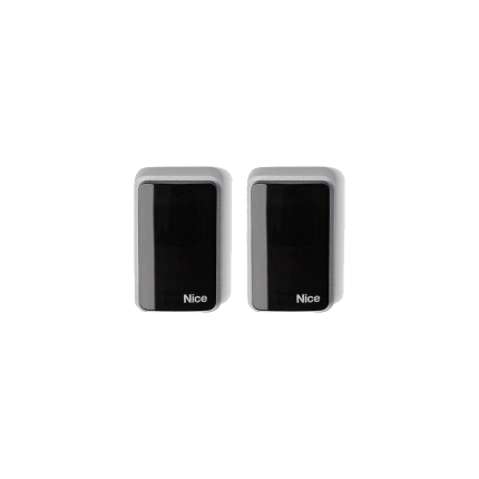
Safety Sensor – Key Automation 900FT33
Ship or pick up from our office.
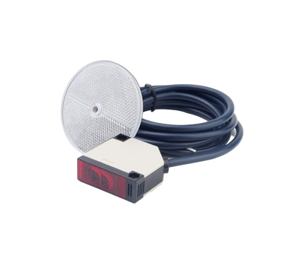
Safety Sensor - Key Automation 900FT33
- NO/NC
- AC 10-30 V / DC 10-40 V
- Receiving Range: 25 Meters
- IP 54
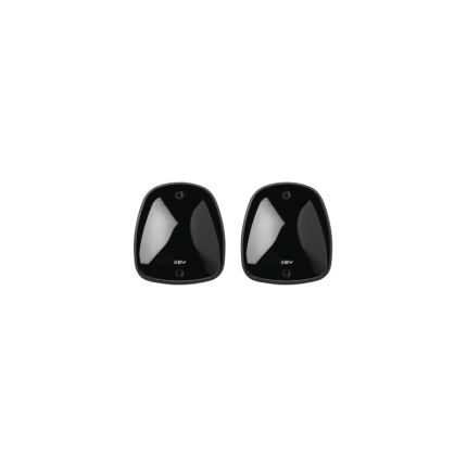
Safety sensor – Nice Era-EPM
Ship or pick up from our office.
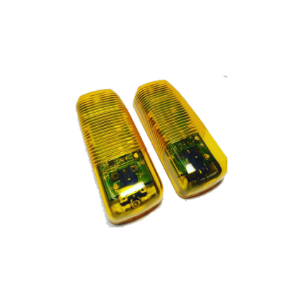
Safety sensor - Nice Era-EPM
The Nice Era-EPM is a photoelectric safety sensor commonly used in automation systems for gates, garage doors, barriers, and similar installations. It's also often referred to as a photocell or beam sensor. Here's a breakdown of what it is and its key features: Purpose: Its primary function is to enhance safety by detecting obstacles in the path of a moving gate or door. It consists of a transmitter (TX) and a receiver (RX) that are installed facing each other. The transmitter emits an infrared beam, and if this beam is interrupted by an object, the receiver signals the control unit to stop or reverse the automation system, preventing accidents, injuries, or damage to vehicles. Key Features and Specifications:- Photoelectric Technology: It uses an infrared beam to detect obstructions.
- Transmitter (TX) and Receiver (RX): Comes as a pair, with one unit transmitting the beam and the other receiving it.
- Relay Output: It's a relay photocell, meaning it sends a signal to the control unit via a relay output.
- Range: Typically has a useful range of 15 meters, which can be extended up to 30 meters in some configurations (e.g., by cutting a "+10m" electrical bridge). However, range can be reduced in adverse weather conditions like fog, rain, or dust.
- Anti-Glare Circuitry: Designed with an anti-glare circuit to minimize interference from sunlight, ensuring reliable performance in various lighting conditions.
- Durable Construction: Features an ABS body that is resistant to weather conditions, making it suitable for outdoor use (IP44 protection rating).
- Easy Installation: Known for its simplified assembly and installation procedure. Some versions (like those with Nice BlueBUS technology) require only two wires for connection to compatible control units, simplifying wiring.
- Wide Angle of Reception: Generally has a 10° (or 8° with a reduction cone) angle of reception, which helps in compensating for minor alignment issues.
- Compatibility: While it's a Nice-branded product, it's often described as a "universal photocell" compatible with most gate and garage door automation systems, especially those that accept standard relay inputs. Some models also feature Nice BlueBUS technology for seamless integration with Nice control units that support it.
- Safety Compliance: It is a Type D presence detector according to EN 12453 standard, which means it detects obstacles on the optical axis. When connected to a control unit with a "phototest" function, it can achieve Category 2 safety against malfunctions according to EN 954-1.