Shop
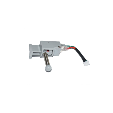
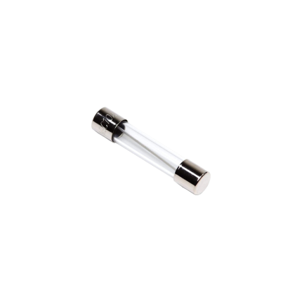
Sliding gate operators limit sensor -Spring
Ship or pick up from our office.
Sliding gate operator limit sensor -Spring
A sliding gate operator limit sensor with a spring mechanism (also known as a mechanical limit switch or spring limit switch) is a common type of sensor used in automatic sliding gate systems to define the gate's fully open and fully closed positions. Here's how it works and what its characteristics are: Purpose of a Limit Sensor: For any automatic gate operator, the system needs to know exactly when the gate has reached its desired open and closed positions. This is crucial for:- Stopping the Motor: Preventing the motor from continuing to run once the gate has reached its limit, which would otherwise cause damage to the gate, the motor, or the track.
- Safety: Ensuring the gate stops precisely where it should, preventing it from hitting obstacles or over-extending.
- Proper Operation: Allowing for features like auto-closing, pedestrian mode, and proper synchronization if it's a dual-gate system.
- Components: A spring limit switch typically consists of:
- A microswitch (an electrical switch that requires very little force to operate).
- A spring-loaded lever, arm, or plunger connected to the microswitch.
- A mounting bracket to attach it to the gate operator or gate frame.
- Mounting: The spring limit switch is usually positioned on the gate operator itself, or on a bracket near the motor.
- Interaction with the Gate:
- On the sliding gate itself, usually along the gear rack or a specific part of the gate frame, two small "stop" tabs or flags are installed – one for the open limit and one for the close limit.
- As the gate moves towards its fully open or fully closed position, one of these tabs/flags will physically contact and push against the spring-loaded lever/plunger of the limit switch.
- This physical contact compresses the spring and activates the microswitch.
- Signal to Control Board: When the microswitch is activated, it sends an electrical signal to the gate operator's main control board.
- Motor Stop: Upon receiving this signal, the control board immediately cuts power to the motor, stopping the gate precisely at that determined limit.
- Physical Contact: The defining feature is that it relies on direct physical contact and force to activate the switch.
- Reliability: Generally reliable as they are a simple mechanical system.
- Durability: Made to withstand repeated physical contact. However, over time, the spring can wear out, lose tension, or the switch itself can be damaged by repeated impacts or debris.
- Adjustability: The position of the "stop" tabs on the gate can be adjusted to fine-tune the exact open and closed positions of the gate.
- Maintenance: May require periodic checks to ensure the spring is intact, the switch is clean, and the "stop" tabs are securely in place and correctly positioned. They can be susceptible to damage from impacts (e.g., if a child's toy or a pet gets in the way of the stop tab).
- Compared to Magnetic Limit Switches:
- Magnetic Limit Switches: These are more common in newer and higher-end gate operators (like many BFT Deimos "Ultra" models). They use magnets attached to the gate and magnetic sensors (reed switches or Hall effect sensors) on the operator. They offer a "contactless" operation, which generally leads to less wear and tear, greater precision, and less susceptibility to environmental debris or physical impact damage.
- Spring/Mechanical Limit Switches: Are typically more cost-effective and simpler in design. They are still widely used, especially in more budget-friendly or older gate operator models.
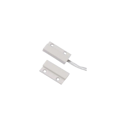
Magnetic Contact Switch – Wired
Ship or pick up from our office.
Magnetic Contact Switch
A magnetic contact switch, often simply called a magnetic contact or door/window sensor, is a simple yet highly effective security device that detects when a door, window, gate, or any movable barrier is opened or closed. How it Works: It consists of two main parts:- The Sensor Unit (with a Reed Switch): This part contains a reed switch. A reed switch is a small, hermetically sealed (airtight) glass capsule with two tiny, flexible magnetic metal reeds (or contacts) inside. These reeds are usually made of a ferromagnetic material. This sensor unit is typically mounted on the stationary part of the opening (e.g., the door frame, window frame, or gate post).
- The Magnet Unit: This part contains a small, permanent magnet. This unit is mounted on the moving part of the opening (e.g., the door itself, the window sash, or the gate panel).
- Closed Position (Circuit Complete): When the door/window/gate is closed, the magnet unit is in very close proximity to the sensor unit. The magnetic field from the permanent magnet pulls the two tiny reeds inside the glass capsule together, causing them to make electrical contact. This completes an electrical circuit, indicating that the opening is secured.
- Many common contacts are "Normally Open" (NO), meaning the circuit is open when the magnet is away and closes when the magnet is near.
- Some are "Normally Closed" (NC), meaning the circuit is closed when the magnet is near and opens when the magnet is away. This is very common in security systems, as an "open" circuit triggers an alarm.
- Opened Position (Circuit Broken/Changed): When the door/window/gate is opened, the magnet moves away from the reed switch. As the magnetic field weakens, the reeds spring back to their original position, breaking the electrical contact. This change in the circuit (from closed to open, or open to closed, depending on the type) signals the connected system (e.g., a car alarm, home security system, or gate control panel) that the opening has occurred.
- Security Systems (Homes, Businesses, Vehicles): This is the most prevalent use. Magnetic contacts are placed on:
- Doors and Windows: To detect unauthorized entry. When a door or window is opened, it triggers the alarm.
- Garage Doors/Overhead Doors: Larger, more robust magnetic contacts are used for garage doors.
- Gates: Used on pedestrian gates or even main driveway gates (sometimes in conjunction with the gate opener's own limit switches) to monitor their open/closed status for security purposes.
- Safes and Vaults: To detect if they have been opened.
- Vehicle Doors/Trunks/Hoods: While vehicles have internal sensors, magnetic contacts can be added for enhanced security on specific compartments or custom modifications.
- Access Control Systems: To monitor entry and exit points, log access events, or control other devices based on door status.
- Automation Systems: To trigger actions based on the status of a movable part. Examples include:
- Turning lights on/off when a door opens.
- Indicating when a cabinet door is ajar.
- Position sensing in industrial machinery.
- Appliance Safety: Some appliances use magnetic contacts to ensure a lid is closed or a guard is in place before operation.
- Surface Mount: Most common, easily screwed or adhered to the surface of the frame and door.
- Recessed/Flush Mount: Designed to be drilled into the frame and door for a more discreet, hidden installation.
- Heavy Duty/Overhead Door Contacts: Larger and more rugged, built for the heavier use and larger gaps often found with garage or industrial doors.
- Wired vs. Wireless:
- Wired: Physically connected to the alarm panel via wires, offering high reliability.
- Wireless: Contain a small battery and a radio transmitter to send signals wirelessly to the alarm panel, offering easier installation.
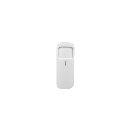
PIR Infrared Sensor – wireless
Ship or pick up from our office.
PIR Infrared Sensor – wireless
A wireless PIR (Passive Infrared) sensor is a type of motion detector that uses infrared technology to detect the presence and movement of people, animals, or other warm objects within its field of view, and then transmits this information wirelessly to a central control unit. Here's a breakdown of its key aspects: PIR (Passive Infrared) Technology:- Passive: The "passive" in PIR means the sensor does not emit any energy (like radar or ultrasonic sensors do). Instead, it "passively" detects the infrared radiation (heat energy) naturally emitted by all objects with a temperature above absolute zero.
- Infrared Detection: All living beings (humans, pets) and warm objects emit infrared radiation.
- How it works: A PIR sensor typically has two sensing elements within its housing. When no motion is present, both elements detect the same amount of infrared radiation from the ambient environment. When a warm body moves across the sensor's field of view, it first enters one sensing element's range, causing a rapid change in the infrared energy detected by that element. As the body moves further, it then affects the second element. This differential change in infrared energy between the two elements is what the sensor interprets as motion.
- Fresnel Lens: PIR sensors often have a specialized faceted lens (a Fresnel lens) on their front. This lens helps to focus the infrared radiation onto the sensing elements and creates multiple "detection zones" or "fingers" within the sensor's field of view, which increases its coverage and sensitivity.
- No Wires for Communication: The "wireless" aspect means the sensor communicates with the alarm system's control panel (or receiver) using radio frequencies (RF) rather than physical wires.
- Battery Powered: Wireless PIR sensors are usually battery-powered, making them easy to install anywhere without needing to run electrical wiring. The batteries typically last for a significant period (months to years) before needing replacement.
- Transmitter: Each sensor has a small radio transmitter that sends a signal to the central alarm panel when motion is detected.
- Receiver: The alarm control panel has a built-in or external wireless receiver that listens for signals from the PIR sensors (and other wireless sensors like door/window contacts).
- Easy Installation: No need for complex wiring, making DIY installation simpler and reducing labor costs for professional installers. This is a significant advantage in existing structures where running wires might be difficult or aesthetically unappealing.
- Flexible Placement: Can be mounted virtually anywhere within their effective range of the control panel, providing versatile coverage.
- Reduced False Alarms (Compared to Simple Motion Detectors): Because PIR sensors detect heat signatures, they are less likely to be triggered by non-living things like swaying curtains, blowing leaves, or shadows (though extreme drafts or sudden temperature changes can still be an issue if not properly installed).
- Pet Immunity: Many wireless PIR sensors offer "pet immunity" features. These sensors are designed to ignore the infrared signatures of smaller animals (below a certain weight, e.g., 40 lbs or 80 lbs), helping to prevent false alarms in homes with pets. This is achieved by adjusting the sensor's lens and internal logic to focus on specific infrared patterns that are indicative of human-sized targets.
- Energy Efficiency: As passive devices, they consume very little power, contributing to long battery life.
- Comprehensive Coverage: Ideal for protecting large areas or rooms, as a single sensor can cover a significant space.
- Integration: Seamlessly integrate with smart home security systems, allowing for remote monitoring, alerts via smartphone apps, and sometimes even integration with other smart devices (e.g., turning on lights when motion is detected).
- Home Security Systems: Widely used indoors to detect intruders in living rooms, hallways, bedrooms, and basements. Outdoor-rated versions are also available for perimeter protection.
- Commercial Security Systems: Protecting offices, warehouses, retail spaces, and other commercial properties.
- Automated Lighting: Activating lights in rooms, hallways, or outdoor areas when someone enters.
- Smart Home Automation: Triggering various smart home routines based on occupancy (e.g., adjusting thermostat, playing music).
- Access Control: Monitoring movement in restricted areas.
- Placement: Proper placement is crucial to avoid false alarms. Avoid aiming them directly at heat sources (vents, radiators, direct sunlight, fireplaces), areas with strong drafts, or windows (especially those exposed to direct sun or busy outdoor activity).
- Pet Immunity Settings: If you have pets, ensure the sensor has pet immunity and that it's set correctly for your pet's size and the sensor's mounting height.
- Signal Range: Ensure the sensor is within the wireless range of your alarm panel, considering walls and other obstructions that might weaken the signal.
- Battery Life: Be mindful of battery replacement schedules to ensure continuous operation.

Solar charge controller
Ship or pick up from our office.
Solar charge controller
A solar charge controller is an electronic device that regulates the flow of electricity from solar panels to a battery bank, protecting the batteries from overcharging and over-discharging. It's a crucial component in off-grid and hybrid solar power systems. Key Functions of a Solar Charge Controller- Preventing Overcharging: Solar panels can produce varying amounts of electricity depending on sunlight intensity. If this unregulated power is sent directly to batteries, it can lead to overcharging, which damages the batteries, reduces their lifespan, and can even pose a safety risk (e.g., overheating, gassing). The charge controller monitors the battery's voltage and reduces or stops the current flow when the battery reaches its full charge.
- Preventing Over-discharging: Some charge controllers also have a low voltage disconnect (LVD) feature that protects the battery from being excessively drained. Deep discharging can also cause irreversible damage to batteries. The controller will disconnect the load when the battery voltage drops below a certain threshold.
- Optimizing Charging: Modern charge controllers use advanced technologies to ensure the batteries are charged efficiently, maximizing the energy harvested from the solar panels.
- Reverse Current Prevention: At night, when solar panels aren't producing power, there's a risk of electricity flowing back from the batteries to the panels, which would drain the batteries. Charge controllers include a diode or similar mechanism to prevent this reverse current flow.
- System Protection: Many controllers offer additional safeguards against issues like short circuits, overloads, and reverse polarity.
- How they work: PWM controllers regulate the voltage by rapidly switching the solar panel input on and off. The "width" of these pulses is adjusted to control the average voltage and current sent to the battery. When the battery is nearly full, the pulses become shorter, reducing the charging current.
- Advantages: They are generally less expensive and simpler in design, making them suitable for smaller, less complex solar systems (e.g., small RV setups, solar lighting).
- Disadvantages: They are less efficient than MPPT controllers, especially in conditions where the solar panel's voltage significantly differs from the battery voltage. They essentially "pull down" the solar panel's voltage to match the battery, leading to energy loss.
- How they work: MPPT controllers are more sophisticated. They can "track" the maximum power point (MPP) of the solar panel. The MPP is the optimal combination of voltage and current at which the solar panel produces the most power. The MPPT controller converts any excess voltage from the solar panels into additional current, thereby maximizing the energy sent to the battery. It's like an automatic transmission that adjusts the gear to get the most power from the engine.
- Advantages: They are significantly more efficient than PWM controllers (often 10-30% more, especially in colder temperatures or when the battery is deeply discharged). They are ideal for larger, more complex solar systems and those where the solar panel array voltage is higher than the battery bank voltage. This also allows for longer wiring runs with less power loss.
- Disadvantages: MPPT controllers are more expensive due to their advanced technology.
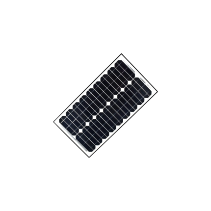
Solar panel
Ship or pick up from our office.
Solar panel
A gate operator solar panel is a component of a solar-powered gate opener system. Its primary function is to convert sunlight into electricity, which then powers the automatic gate and charges its battery. Here's a breakdown of what that means and how it works: How it Works:- Solar Energy Capture: The solar panel, typically made of photovoltaic (PV) cells, captures sunlight.
- Electricity Generation: The PV cells convert the sunlight into direct current (DC) electrical energy.
- Charging the Battery: This electrical energy is sent to a control box, where it charges a battery (often a deep-cycle marine battery or a specialized gate opener battery).
- Powering the Gate: The stored energy in the battery is then used to power the gate's motor and control system, allowing it to open and close.
- Backup Power: The battery acts as a backup, ensuring the gate can function even at night, during cloudy periods, or during power outages when the solar panel isn't generating enough electricity.
- Solar Panel: The component that captures sunlight and converts it into electricity. These come in various wattages (e.g., 5W, 10W, 20W, 40W, 60W, 90W, 120W), with the appropriate size depending on gate usage and accessories.
- Battery: Stores the electrical energy generated by the solar panel.
- Charge Controller/Regulator: Manages the flow of electricity from the solar panel to the battery, preventing overcharging and optimizing efficiency.
- Gate Operator/Motor: The mechanism that actually opens and closes the gate (can be for swing gates, slide gates, or barrier gates).
- Control Box: Houses the battery and control system for the gate operator.
- Mounting Bracket and Hardware: Used to securely install the solar panel.
- Wiring: Connects the solar panel to the control box and battery.
- Grid Independence: Ideal for remote areas or properties without easy access to the main power grid.
- Cost Savings: Reduces or eliminates electricity bills associated with operating a gate.
- Eco-Friendly: Utilizes a renewable, clean energy source, reducing reliance on fossil fuels.
- Power Outage Resilience: Continues to operate during power outages due to the stored battery power.
- Enhanced Safety: Often operate at lower voltage levels than AC systems, reducing the risk of electric shock.
Gate operator control board fuse
Ship or pick up from our office.
Gate operator control board fuse
A gate operator control board fuse is a critical safety component found on the circuit board of an automatic gate system. Its primary function is to protect the electrical components of the gate operator from damage caused by excessive current, such as a short circuit or an overload. Essentially, it acts as a sacrificial link in the electrical circuit. If the current flowing through the circuit exceeds a predetermined safe limit, the thin metal wire or strip inside the fuse melts and breaks the circuit. This prevents the surge of electricity from reaching and damaging more expensive and vital components on the control board or in the motor. Types and Characteristics Gate operator control board fuses come in various amperage ratings, typically ranging from 0.2 to 15 amps, depending on the specific gate operator model and its power requirements. Some common characteristics include:- Slow-Blow/Time-Delay Fuses: Many gate operators use "slow-blow" or "time-delay" fuses. These fuses are designed to tolerate brief, temporary current surges that often occur when motors start up without immediately blowing. They only interrupt the circuit if the overload persists for a longer duration.
- Physical Form: They can be found in various physical forms, including glass tube fuses (common in older models), blade-style automotive fuses, or sometimes as surface-mount fuses directly on the printed circuit board.
- Short Circuit: A direct path for current to flow, bypassing the normal resistance, causing a sudden and large surge.
- Overload: The gate motor or another component drawing more current than it's designed for, perhaps due to mechanical obstruction, a faulty motor, or issues with the gate's movement (e.g., binding hinges, gate dragging on the ground).
- Component Failure: A faulty component on the control board or within the gate operator system itself can cause an abnormal current draw, leading the fuse to blow.
- Power Surges: External power surges from the main electrical supply or lightning strikes can also cause fuses to blow.
- Disconnect Power: Always disconnect all power to the gate operator before attempting any inspection or repair. This includes both AC power and any battery backup systems.
- Locate the Fuse: The fuse is typically located directly on the main control board, often in a small holder or a clear cover. Refer to your gate operator's manual for its exact location.
- Inspect the Fuse:
- For glass tube fuses, you can often visually inspect the wire inside; if it's broken or discolored, the fuse is blown.
- For blade-style fuses, there might be a visible break in the metal strip, or you can use a multimeter set to continuity mode. A blown fuse will show no continuity.
- Replace the Fuse: If the fuse is blown, replace it with a new fuse of the exact same amperage (ampere) and voltage rating. Using a fuse with a higher rating can lead to damage to the control board or other components, as it won't blow when it should. Using a lower rating may cause the fuse to blow unnecessarily.
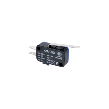
Micro Limit Switch
Ship or pick up from our office.
Micro Limit Switch
A micro limit switch, often simply called a micro switch, is a type of electrical switch that's characterized by its small size and the precise, rapid action it takes when a minimal amount of force is applied to its actuator. It's designed to detect the presence or position of an object or the end of a mechanical movement. These switches are known for their:- High sensitivity: They require very little force to activate.
- Rapid response: The internal contacts "snap" open or closed very quickly, regardless of how slowly the actuator is pressed. This snap-action mechanism helps to reduce arcing and extends the switch's lifespan.
- Reliability: They are built to withstand millions of operations, making them durable for long-term use.
- Compact size: Their small footprint allows them to be used in applications where space is limited.
- Actuator: This is the external part that an object or mechanical component presses against. It can be a button, a lever (with or without a roller), a plunger, or other forms.
- Internal spring mechanism: This provides the "snap-action." When the actuator is pressed to a certain point (the "trip point"), the spring mechanism rapidly moves the contacts.
- Contacts: These are the electrical components that open or close the circuit. Micro switches usually have three terminals:
- Common (C): The input terminal.
- Normally Open (NO): This contact is open (no current flows) when the switch is unactivated and closes when the switch is actuated.
- Normally Closed (NC): This contact is closed (current flows) when the switch is unactivated and opens when the switch is actuated
- Household Appliances:
- Microwave ovens: To detect if the door is closed before operating.
- Washing machines: For door interlocks and water level detection.
- Refrigerators: To turn the light on/off when the door opens/closes.
- Printers: To detect paper jams or the position of paper.
- Automotive Industry:
- Car doors: To detect if a door is open or closed (e.g., for interior lights or security systems).
- Brake pedals: To activate brake lights.
- Seat belt mechanisms: To detect if a seat belt is fastened.
- Industrial Automation:
- Conveyor systems: To detect the presence of items or the end of travel for a belt.
- Robotic arms: For precise positioning and limit detection of movement.
- Machine safety guards: To ensure guards are correctly positioned before machinery operates.
- Elevators and hoists: To prevent over-travel and ensure proper door operation.
- Consumer Electronics:
- Computer mice and keyboards: For button clicks.
- Vending machines: For coin detection or jam detection.
- Medical Equipment:
- In various diagnostic tools and surgical instruments for precise control.
- Pin Plunger: A simple button-like plunger that is directly pressed.
- Roller Lever: Features a lever with a roller at the end, ideal for applications with sliding or rotating components.
- Hinge Lever: A simple lever arm that pivots to actuate the switch.
- Flexible Roller: Similar to a roller lever, but with a more flexible arm to accommodate irregular surfaces or wider ranges of motion.
- Spring Plunger: A plunger supported by a spring, allowing for a certain degree of "overtravel" beyond the actuation point without damaging the switch.
Mercury Level Switch
Ship or pick up from our office.
Mercury Level Switch
A mercury level switch is a type of electrical switch that uses a small amount of liquid mercury to open or close an electrical circuit based on its position or the level of a liquid. Essentially, the mercury acts as a conductive bridge between electrical contacts. How it Works The core component of a mercury level switch is a sealed glass or metal capsule containing one or more electrical contacts and a small, free-moving drop of mercury. When the switch or the liquid it's monitoring changes its tilt or level:- Tilt Switches: Gravity pulls the mercury to the lowest point within the capsule. If the tilt is sufficient, the mercury will flow to connect two or more contacts, completing an electrical circuit. Tilting it in the opposite direction moves the mercury away, breaking the circuit.
- Float Switches: In liquid level applications, the mercury switch is often integrated with a float mechanism. As the liquid level rises or falls, the float moves, which in turn tilts the mercury switch, causing the mercury to connect or disconnect the contacts.
- Displacement Switches: Some designs use a "plunger" that dips into a pool of mercury, raising the mercury level to contact an electrode and complete the circuit.
- Thermostats: In older thermostats, they controlled heating and cooling systems.
- Sump Pumps: Used to automatically turn on the pump when water levels rise.
- Appliances: Found in washing machines (for lid switches and load balancing), chest freezers (for lid lights), and some gas appliances like ovens and water heaters (as flame sensors).
- Automotive Industry: Previously used for trunk lid lights, ride control, and anti-lock braking systems.
- Industrial Settings: Utilized in liquid level control and safety systems.
- Roll Sensing/Tip-over Warnings: For construction equipment or other vehicles operating on uneven terrain.
- Durability and Reliability: The sealed contacts prevent oxidation, leading to a long lifespan.
- Quiet Operation: No abrupt snapping of contacts.
- No Contact Erosion: Mercury's liquid nature prevents the wear and tear seen in mechanical contacts.
- Spark-Free: They don't produce sparks when making or breaking circuits, making them suitable for hazardous environments.
- Toxicity of Mercury: This is the primary and most significant disadvantage. Mercury is a highly toxic substance, posing serious environmental and health risks if released.
- Environmental Concerns: Improper disposal of mercury switches can lead to widespread contamination. Due to these concerns, the use of mercury switches has been largely phased out in many applications, especially in new products.
- Sensitivity to Gravity/Orientation: While an advantage for tilt sensing, it makes them unsuitable for portable or mobile devices where orientation changes or vibrations could cause false readings.
- Limited Functionality: Most mercury switches provide only a simple on/off function.

Metal Case Diode Bridge KBPC5010
Ship or pick up from our office.
Metal Case Diode Bridge KBPC5010
The Metal Case Diode Bridge KBPC5010 is a specific type of bridge rectifier, a crucial electronic component used to convert alternating current (AC) into direct current (DC). It is widely employed in various power supply applications. Here's a breakdown of its key features and what each part of its name signifies: What is a Bridge Rectifier? A bridge rectifier is a circuit of four (or more) diodes in a specific configuration that allows for full-wave rectification. This means it efficiently converts both the positive and negative half-cycles of an AC input into a pulsating DC output. Compared to simpler half-wave rectifiers, bridge rectifiers are more efficient and provide a smoother DC output.- KBPC: This is typically a series designation for a family of single-phase bridge rectifiers with specific package styles.
- 50: This number indicates the maximum average forward rectified current (Io) the device can handle, which in this case is 50 Amperes (A). This high current rating makes it suitable for demanding applications.
- 10: This number typically refers to the voltage class, often indicating a maximum repetitive peak reverse voltage (VRRM) of 1000 Volts (V) (where '10' often means 10 x 100V). This high voltage rating allows it to handle substantial AC input voltages.
- Conversion: Converts single-phase AC to pulsating DC.
- Current Rating: Up to 50 Amperes (A) average forward current.
- Voltage Rating: Up to 1000 Volts (V) repetitive peak reverse voltage.
- Surge Current Capability: Often capable of handling high non-repetitive surge currents (e.g., 400A or 450A for a short duration), which is crucial for handling initial power-on transients.
- Low Forward Voltage Drop: Minimizes power loss and improves efficiency.
- High Reliability: Designed for robust performance in various environments.
- Mounting: Typically features through-hole mounting with a screw hole for chassis or heatsink mounting.
- Terminals: Often uses 0.25" (6.35 mm) Faston terminals for easy connection. Some variants (like KBPC5010W) might have wire leads.
- Operating Temperature: Wide operating junction temperature range, often from -40°C to +150°C.
- Power supplies: As a core component to rectify AC mains voltage into DC for electronic devices.
- Battery chargers: Converting AC power to DC for charging batteries.
- Motor control circuits: Providing DC power for electric motors.
- Industrial control systems: Used in various industrial applications requiring AC-to-DC conversion.
- Input rectifiers for variable frequency drives (VFDs).
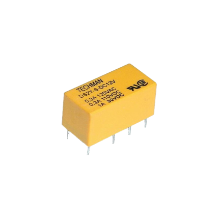
Relay Mini PCB 8-Pin 1A
Ship or pick up from our office.
Relay Mini PCB 8-Pin 1A
A Relay Mini PCB 8-Pin 1A is a small, electronic switch designed to be mounted directly onto a Printed Circuit Board (PCB). It has eight pins for connections and its contacts can safely switch a maximum current of 1 Ampere (1A). Key Characteristics- Miniature Size: The "Mini" in its name indicates its compact dimensions, making it suitable for circuits where space is limited.
- PCB Mountable: It's designed for through-hole soldering onto a PCB, integrating seamlessly into electronic designs.
- 8-Pin Configuration: These pins serve various purposes, including connecting the coil (which activates the relay) and the switch contacts (which control the electrical load).
- 1A Current Rating: This is the maximum current that can safely flow through the relay's contacts when they are closed.
- Coil Voltage: The relay's coil operates on a specific DC voltage (e.g., 3V, 5V, 12V, 24V). Applying this voltage to the coil creates a magnetic field that mechanically opens or closes the contacts.
- Contact Configuration: Many 8-pin mini PCB relays are DPDT (Double Pole, Double Throw), meaning they have two sets of contacts, each with both normally open (NO) and normally closed (NC) positions. This allows for versatile switching operations.
- Isolation: Relays provide electrical isolation between the control circuit (coil) and the load circuit (contacts), enhancing safety and preventing interference.
- Remote Control Systems: Used to switch power to devices based on signals from a remote.
- Communication Equipment: For routing or switching signals in telecommunications and data networks.
- Automatic Control Systems: In automation processes to control motors, lights, or other actuators.
- Household Appliances: Found in various home electronics to manage power to different components.
- Automotive Systems: Employed in vehicles to control functions like lights, locks, and windows.
- Instrumentation and Measurement Devices: For precise signal routing and control in sensitive equipment.
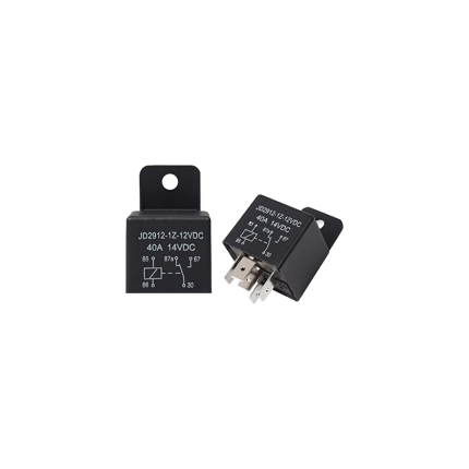
Relay 5-Pin 40A
Ship or pick up from our office.
Relay 5-Pin 40A
A 5-pin 40A relay is an electromechanical switch commonly used in automotive and other applications. It allows a low-power electrical signal to control a higher-power circuit. The "5-pin" refers to the number of terminals it has, and "40A" indicates that its contacts can safely handle a maximum current of 40 amps. How it Works A relay essentially functions like a remote-controlled switch. It has two main circuits:- Control Circuit (Coil): This low-power circuit energizes an electromagnet inside the relay.
- Switched Circuit (Contacts): This high-power circuit is controlled by the electromagnet, either opening or closing connections to a device.
- Pins 85 and 86: These are the coil terminals. When a small current (typically 12V DC in automotive applications) is applied across these pins, it creates a magnetic field.
- Pin 30: This is the common terminal for the switched circuit. It's usually connected to the main power source (e.g., battery) through a fuse.
- Pin 87: This is the Normally Open (NO) contact. When the relay coil is energized, pin 30 connects to pin 87, allowing current to flow to the connected device.
- Pin 87a: This is the Normally Closed (NC) contact. When the relay coil is not energized, pin 30 is connected to pin 87a. When the coil is energized, this connection breaks.
- High-Current Control: They allow you to control high-current devices (like headlights, fuel pumps, or cooling fans) with a low-current switch. This protects the sensitive, smaller switches from being damaged by excessive current.
- Reduced Voltage Drop: By placing the relay closer to the high-current device and power source, you can use shorter runs of heavier gauge wire for the high-current circuit, minimizing voltage drop and ensuring the device receives adequate power.
- Safety: They isolate high-current circuits from the passenger compartment, enhancing safety.
- Automotive: Headlights, fog lights, horns, fuel pumps, electric cooling fans, power windows, central locking, and various aftermarket accessories.
- Industrial Control: Switching motors, solenoids, and other heavy-duty equipment.
- General Purpose: Any application where a low-power signal needs to control a higher-power circuit.
- Pin 85: Connect to ground (-).
- Pin 86: Connect to the positive (+) side of your control switch. When this switch is activated, it provides power to the coil.
- Pin 30: Connect directly to the positive (+) terminal of your battery, always through an appropriately sized fuse.
- Pin 87: Connect to the positive (+) terminal of the device you want to power when the relay is activated (Normally Open connection).
- Pin 87a: (Optional) Connect to a device you want to power when the relay is not activated (Normally Closed connection).
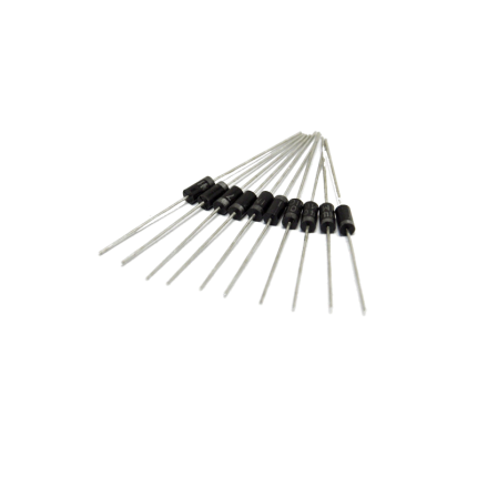
Diode 1N4007
Ship or pick up from our office.
Diode 1N4007
The 1N4007 is a very common and versatile silicon rectifier diode. It's part of the 1N400x series of general-purpose diodes, with the "7" indicating its specific voltage rating. Key Characteristics- Rectifier Diode: Its primary function is to convert alternating current (AC) into pulsating direct current (DC) by allowing current to flow in only one direction.
- High Reverse Voltage Rating: The 1N4007 can withstand a peak repetitive reverse voltage () of 1000V. This makes it suitable for high-voltage applications.
- Average Forward Current: It can handle an average forward current () of 1 Ampere (1A).
- Forward Voltage Drop: When conducting in the forward direction, it has a relatively low forward voltage drop () of approximately 0.7V to 1.1V. This voltage drop represents the power lost within the diode.
- Surge Current Capability: It can handle a non-repetitive peak surge current () of up to 30A for short durations, which is useful for handling initial power-on surges.
- Package Type: It typically comes in a DO-41 axial-lead package, which is a small, cylindrical plastic package with leads on both ends.
- Operating Temperature Range: It operates reliably over a wide temperature range, typically from -55°C to +175°C.
- Forward Bias: When a positive voltage is applied to the anode (P-side) and a negative voltage to the cathode (N-side), the diode is forward-biased. If the applied voltage exceeds the forward voltage drop (around 0.7V for silicon diodes), the diode conducts, allowing current to flow from anode to cathode.
- Reverse Bias: When a negative voltage is applied to the anode and a positive voltage to the cathode, the diode is reverse-biased. In this state, the diode acts like an open switch, blocking current flow. The 1N4007 is designed to withstand up to 1000V in this reverse-biased state before breaking down.
- Rectifier Circuits:
- Half-wave and Full-wave Rectifiers: Essential for converting AC power from the mains (like in household appliances) to DC power for electronic devices.
- Bridge Rectifiers: Used to convert the entire AC waveform into pulsating DC, achieving more efficient rectification.
- Power Supplies: Used for rectifying the AC input in power supply units to provide DC voltage to various components.
- Voltage Protection:
- Reverse Polarity Protection: Prevents damage to circuits if the power supply is connected with incorrect polarity.
- Freewheeling Diodes (Flyback Diodes): Protect sensitive components from voltage spikes generated by inductive loads (like relays, motors, and solenoids) when their magnetic field collapses.
- Voltage Spike Suppression: Helps to suppress transient voltage spikes that can occur due to switching events or lightning, safeguarding delicate electronics.
- Inverters and Converters: Used in various power conversion circuits.
- Current Flow Regulation: Can be used in simple current limiting or flow control applications.


