

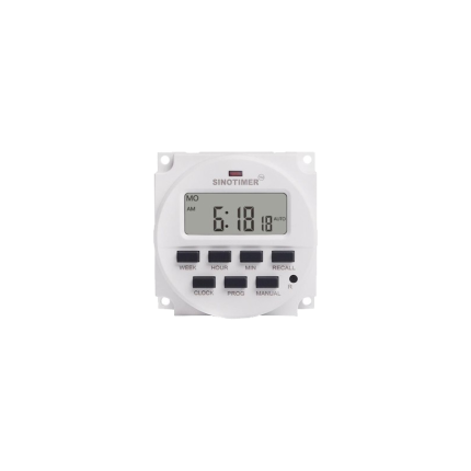
Delay relay 0.5 Sec – AC 24 V to AC 24 V
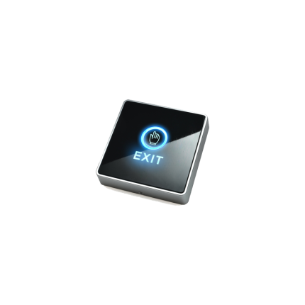
(To use in the electric lock)
A delay relay with a 0.5-second delay, using a 24VAC coil and providing a 24VAC output, is a device that introduces a 0.5-second delay between the application of a 24VAC signal to its coil and the activation of its output contacts, which also switch a 24VAC signal.
This type of relay is commonly used in control systems where a brief delay is needed before a circuit is activated.
Here’s a breakdown:
-
24VAC Coil:The relay’s coil, which is the electromagnet that actuates the relay, is designed to operate with a 24VAC power supply.
-
0.5-second Delay:When the 24VAC coil is energized, the relay does not immediately switch its contacts. Instead, it waits for a specified time (in this case, 0.5 seconds) before the output contacts change state.
-
24VAC Output:The relay’s output contacts are designed to switch a 24VAC signal. When the delay elapses, the contacts will either close (if normally open) or open (if normally closed), allowing the 24VAC signal to pass through or be interrupted, respectively.
-
On-Delay Function:This type of relay is often referred to as an “on-delay” or “delay on operate” relay, meaning the delay occurs when the coil is energized (turned on).
Applications:
-
Preventing Inrush Currents:
Inrush currents can occur when a device is initially powered on, potentially causing damage. A time delay relay can be used to delay the activation of the load, allowing the inrush current to subside before the full load is applied.
-
Sequencing Operations:
Time delay relays can be used to create a sequence of operations, where one action is triggered after a delay from another.
-
Control Systems:
They are frequently used in various control systems to introduce timing elements in the control logic.
-
Compressor Protection:
In HVAC systems, they can be used to prevent short cycling of compressors by introducing a delay between starts.
Example:
Imagine a heating system where a fan needs to start a few seconds after the heating element is energized. A 0.5-second on-delay relay could be used to control the fan, ensuring it turns on slightly after the heater. The 24VAC input signal could come from the thermostat, and the 24VAC output could be connected to the fan motor.


Reviews
There are no reviews yet.