Sliding gate operator
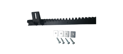
Sliding gate operator gear rack -SLGR41
Ship or pick up from our office.
Sliding gate operator gear rack -SLGR41
*4 Holes *Length: 1018 mm
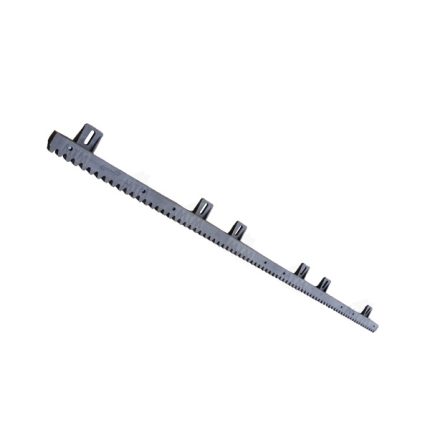
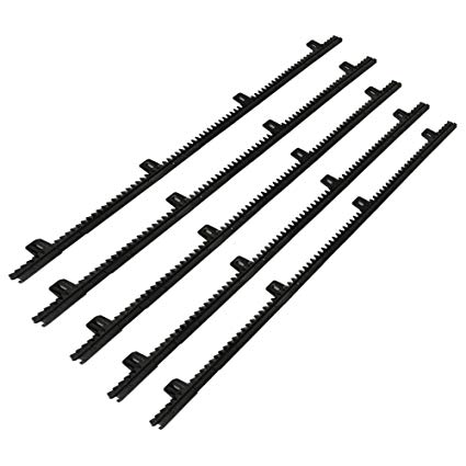
Sliding gate operator gear rack -SLGR612
Ship or pick up from our office.
Sliding gate operator gear rack -SLGR612
*6 Holes *Length: 1018 mm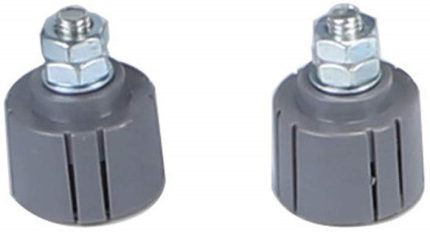
Sliding gate operator limit sensor – Magnetic mechanism
Ship or pick up from our office.
Sliding gate operator limit sensor - Magnetic mechanism
A sliding gate operator limit sensor, often a limit switch, is a crucial component that signals the gate operator when the gate has reached its fully open or fully closed position, stopping the motor and preventing over-travel. These sensors ensure the gate stops at the correct positions, preventing damage to the gate and surrounding structure.
Here's a more detailed explanation:
-
Function:Limit sensors, like limit switches, detect when the gate reaches its extreme open or closed positions.
-
How it works:When the gate reaches the limit, the sensor sends a signal to the gate operator's control board, which then stops the motor.
-
Importance:Without limit sensors, the gate might continue to move, potentially hitting the end posts or other obstructions, causing damage.
-
Types:Common types include magnetic limit switches and photoelectric sensors (photo eyes).
-
Magnetic Limit Switches:These utilize magnets placed on the gate and a magnetic sensor on the operator. When the magnet aligns with the sensor, it triggers the limit switch.
-
Photoelectric Sensors (Photo Eyes):These use infrared beams to detect obstructions. When the beam is broken (e.g., by the gate), the sensor signals the operator to stop.
-
Installation:Proper installation and adjustment of limit sensors are crucial for the reliable operation.
-
Maintenance:Regular inspection and maintenance of limit sensors are recommended, as they can wear out or become misaligned over time.
Sliding gate operator limit sensor -Spring
Ship or pick up from our office.
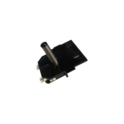
Sliding gate operator limit sensor -Spring
A sliding gate operator limit sensor with a spring mechanism (also known as a mechanical limit switch or spring limit switch) is a common type of sensor used in automatic sliding gate systems to define the gate's fully open and fully closed positions. Here's how it works and what its characteristics are: Purpose of a Limit Sensor: For any automatic gate operator, the system needs to know exactly when the gate has reached its desired open and closed positions. This is crucial for:- Stopping the Motor: Preventing the motor from continuing to run once the gate has reached its limit, which would otherwise cause damage to the gate, the motor, or the track.
- Safety: Ensuring the gate stops precisely where it should, preventing it from hitting obstacles or over-extending.
- Proper Operation: Allowing for features like auto-closing, pedestrian mode, and proper synchronization if it's a dual-gate system.
- Components: A spring limit switch typically consists of:
- A microswitch (an electrical switch that requires very little force to operate).
- A spring-loaded lever, arm, or plunger connected to the microswitch.
- A mounting bracket to attach it to the gate operator or gate frame.
- Mounting: The spring limit switch is usually positioned on the gate operator itself, or on a bracket near the motor.
- Interaction with the Gate:
- On the sliding gate itself, usually along the gear rack or a specific part of the gate frame, two small "stop" tabs or flags are installed – one for the open limit and one for the close limit.
- As the gate moves towards its fully open or fully closed position, one of these tabs/flags will physically contact and push against the spring-loaded lever/plunger of the limit switch.
- This physical contact compresses the spring and activates the microswitch.
- Signal to Control Board: When the microswitch is activated, it sends an electrical signal to the gate operator's main control board.
- Motor Stop: Upon receiving this signal, the control board immediately cuts power to the motor, stopping the gate precisely at that determined limit.
- Physical Contact: The defining feature is that it relies on direct physical contact and force to activate the switch.
- Reliability: Generally reliable as they are a simple mechanical system.
- Durability: Made to withstand repeated physical contact. However, over time, the spring can wear out, lose tension, or the switch itself can be damaged by repeated impacts or debris.
- Adjustability: The position of the "stop" tabs on the gate can be adjusted to fine-tune the exact open and closed positions of the gate.
- Maintenance: May require periodic checks to ensure the spring is intact, the switch is clean, and the "stop" tabs are securely in place and correctly positioned. They can be susceptible to damage from impacts (e.g., if a child's toy or a pet gets in the way of the stop tab).
- Compared to Magnetic Limit Switches:
- Magnetic Limit Switches: These are more common in newer and higher-end gate operators (like many BFT Deimos "Ultra" models). They use magnets attached to the gate and magnetic sensors (reed switches or Hall effect sensors) on the operator. They offer a "contactless" operation, which generally leads to less wear and tear, greater precision, and less susceptibility to environmental debris or physical impact damage.
- Spring/Mechanical Limit Switches: Are typically more cost-effective and simpler in design. They are still widely used, especially in more budget-friendly or older gate operator models.
Sliding gate operator limit stopper bracket
Ship or pick up from our office.
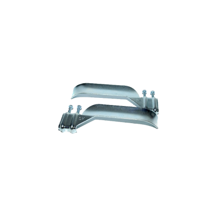
Sliding gate operator limit stopper bracket
The gate operator system with a damaged limit stopper bracket can not work properly, and it will soon stop working. Most of the time, the main control board and the motor will be damaged because of this issue and have to be replaced. Sometimes errors come from the limit stopper bracket not working because they are damaged and needs only to be cleaned or readjustment.A sliding gate operator limit stopper bracket is a component that works with limit switches to prevent a sliding gate from over-extending its travel, ensuring it stops at the desired open and closed positions.
These brackets typically hold magnets or other sensor components that interact with the limit switches on the gate operator's control board. They help maintain the gate's smooth and safe operation by preventing it from hitting obstructions or going off its track.
Here's a more detailed explanation:
-
Purpose:The primary function of the limit stopper bracket is to define the boundaries of the gate's movement. It ensures the gate stops at the fully open and fully closed positions, preventing it from over-traveling.
-
How it works:The bracket holds a magnetic or other type of sensor that is triggered when the gate reaches its limit. This trigger sends a signal to the gate operator's control board, which then stops the motor.
-
Components:
- Bracket: The physical structure that holds the sensor.
- Sensor: A device (often a magnet) that interacts with the limit switch.
- Limit Switch: A switch on the gate operator's control board that is activated by the sensor.
- Bracket: The physical structure that holds the sensor.
-
Importance:
- Safety: Prevents the gate from hitting objects or going off track, reducing the risk of damage or injury.
- Reliability: Ensures consistent and reliable gate operation by defining the travel limits.
- Protection: Protects the gate, operator, and surrounding objects from damage due to over-travel.
- Safety: Prevents the gate from hitting objects or going off track, reducing the risk of damage or injury.
Sliding gate operator main control board – Key Automation
Ship or pick up from our office.
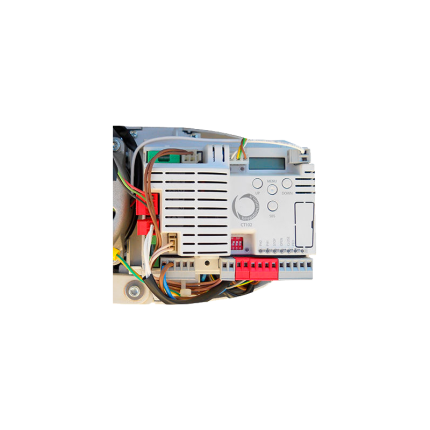
Sliding gate operator main control board – Key Automation
The main control board for a Key Automation sliding gate operator, like the SUN7224 or SUN11024, is the central processing unit that manages the gate's movement, safety features, and other functionalities.
It receives signals from remote controls, keypads, or sensors, and then directs the motor to open or close the gate accordingly.
Here's a more detailed explanation:
-
Core Function:The control board acts as the "brain" of the gate system, interpreting signals and controlling the motor.
-
Input:It receives signals from various input devices, such as remote controls, keypads, or safety sensors.
-
Output:It sends commands to the motor to start, stop, reverse, or adjust its speed based on the input received.
-
Safety Features:Many control boards include safety features like obstacle detection, which can automatically stop or reverse the gate if it encounters an obstruction.
-
Programming and Diagnostics:Some control boards offer programming capabilities and diagnostic displays to simplify setup and troubleshooting.
-
D-Track Technology:Some Key Automation models, like the Deimos, utilize D-Track technology for precise torque management and impact detection.
-
Power Supply:Control boards typically operate on a specific voltage (e.g., 24V DC or 110V AC).
Sliding gate operator main control board – Zero
Ship or pick up from our office.
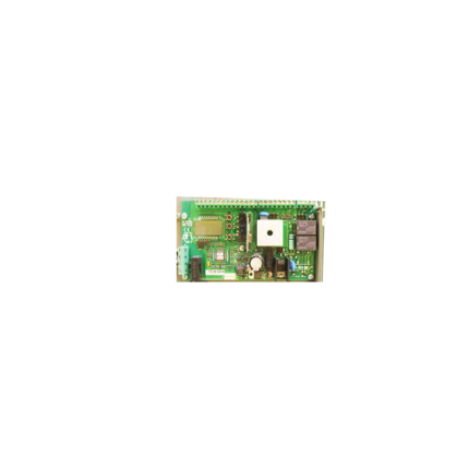
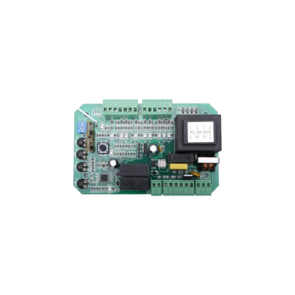
Sliding gate operator main control board – Zero
The sliding gate operator main control board (also referred to as a PCB or circuit board) is the central component that manages all the functions of an automatic sliding gate system.
It acts as the "brain" of the gate, receiving signals from various input devices (like remote controls, keypads, or safety sensors) and translating them into actions for the gate's motor and other components.
Here's a more detailed breakdown:
1. Central Control: The control board is the central hub for all gate operations. It receives signals from different sources, such as:
- Remote controls: For opening and closing the gate.
- Keypads: For authorized access.
- Safety sensors: To detect obstructions and prevent accidents.
- Other accessories: Such as loop detectors, intercom systems, etc.
2. Signal Processing: The control board interprets the signals it receives and determines the appropriate action for the gate.
3. Motor Activation: Based on the processed signal, the control board sends instructions to the gate's motor to either open or close the gate.
4. Adjustable Settings: The control board often allows for adjustments to various parameters, including:
- Gate speed: The speed at which the gate opens and closes.
- Opening and closing timers: To control the duration of the gate's movement.
- Safety features: Including force adjustments, obstacle detection sensitivity, and slow-down settings.
Sliding gate operators limit sensor -Spring
Ship or pick up from our office.
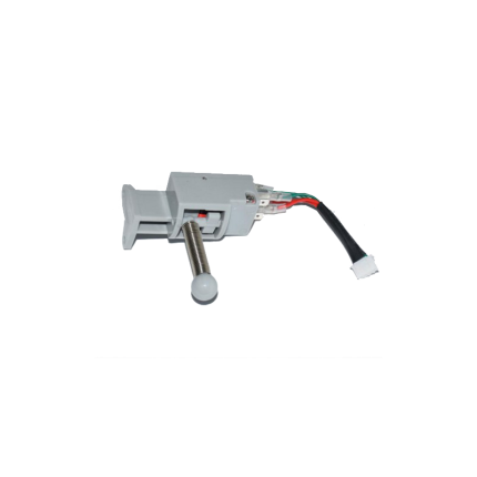
Sliding gate operator limit sensor -Spring
A sliding gate operator limit sensor with a spring mechanism (also known as a mechanical limit switch or spring limit switch) is a common type of sensor used in automatic sliding gate systems to define the gate's fully open and fully closed positions. Here's how it works and what its characteristics are: Purpose of a Limit Sensor: For any automatic gate operator, the system needs to know exactly when the gate has reached its desired open and closed positions. This is crucial for:- Stopping the Motor: Preventing the motor from continuing to run once the gate has reached its limit, which would otherwise cause damage to the gate, the motor, or the track.
- Safety: Ensuring the gate stops precisely where it should, preventing it from hitting obstacles or over-extending.
- Proper Operation: Allowing for features like auto-closing, pedestrian mode, and proper synchronization if it's a dual-gate system.
- Components: A spring limit switch typically consists of:
- A microswitch (an electrical switch that requires very little force to operate).
- A spring-loaded lever, arm, or plunger connected to the microswitch.
- A mounting bracket to attach it to the gate operator or gate frame.
- Mounting: The spring limit switch is usually positioned on the gate operator itself, or on a bracket near the motor.
- Interaction with the Gate:
- On the sliding gate itself, usually along the gear rack or a specific part of the gate frame, two small "stop" tabs or flags are installed – one for the open limit and one for the close limit.
- As the gate moves towards its fully open or fully closed position, one of these tabs/flags will physically contact and push against the spring-loaded lever/plunger of the limit switch.
- This physical contact compresses the spring and activates the microswitch.
- Signal to Control Board: When the microswitch is activated, it sends an electrical signal to the gate operator's main control board.
- Motor Stop: Upon receiving this signal, the control board immediately cuts power to the motor, stopping the gate precisely at that determined limit.
- Physical Contact: The defining feature is that it relies on direct physical contact and force to activate the switch.
- Reliability: Generally reliable as they are a simple mechanical system.
- Durability: Made to withstand repeated physical contact. However, over time, the spring can wear out, lose tension, or the switch itself can be damaged by repeated impacts or debris.
- Adjustability: The position of the "stop" tabs on the gate can be adjusted to fine-tune the exact open and closed positions of the gate.
- Maintenance: May require periodic checks to ensure the spring is intact, the switch is clean, and the "stop" tabs are securely in place and correctly positioned. They can be susceptible to damage from impacts (e.g., if a child's toy or a pet gets in the way of the stop tab).
- Compared to Magnetic Limit Switches:
- Magnetic Limit Switches: These are more common in newer and higher-end gate operators (like many BFT Deimos "Ultra" models). They use magnets attached to the gate and magnetic sensors (reed switches or Hall effect sensors) on the operator. They offer a "contactless" operation, which generally leads to less wear and tear, greater precision, and less susceptibility to environmental debris or physical impact damage.
- Spring/Mechanical Limit Switches: Are typically more cost-effective and simpler in design. They are still widely used, especially in more budget-friendly or older gate operator models.
Sliding gate V-Groove nylon wheels -SLGWN778MLB
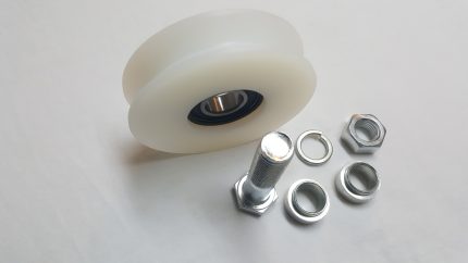
Sliding gate V-Groove nylon wheels -SLGWNS250
Ship or pick up from our office.
*Double bearing *Max 250 Kg *98 mm Diameter (4") x 44 mm Width (1-3/4") (Heavy-duty bolts, nuts, and washers are included)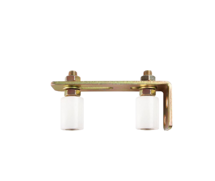
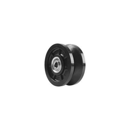
Support Roller
Ship or pick up from our office.
Support Roller
Support Roller for sliding gates are essential components that ensure smooth, stable, and reliable gate operation.
They guide the gate along its track, preventing it from tipping or falling off and ensuring it opens and closes with minimal friction and noise.
Function:
-
Guidance:Support rollers are typically mounted on the gate posts and guide the gate along its track as it opens and closes.
-
Stability:They keep the gate upright and prevent it from swaying or falling out of alignment, especially in windy conditions or with heavier gates.
-
Smooth Operation:By minimizing friction, they allow the gate to slide easily and quietly, enhancing the user experience.
-
Durability:They are designed to withstand the wear and tear of regular use and exposure to the elements.
Types:
- Nylon Rollers: Often used due to their durability, smooth operation, and resistance to corrosion.
- Rubber Rollers: While cheaper, they may leave marks on the gate and wear out faster.
- V-Groove Wheels: Suitable for specific track types and known for their longevity.
Installation:
- Positioning: Support rollers are typically installed on the gate posts, positioned to guide the gate along its track.
- Spacing: A gap of 5-10mm is usually recommended between rollers to allow for some movement and prevent them from doing all the work, especially if the gate is not perfectly balanced.
- Fixation: They are usually secured with bolts or by welding them to the post.
Maintenance:
-
Lubrication:Applying a silicone-based lubricant to the support rollers and other moving parts can help maintain smooth operation and reduce noise.
-
Regular Inspection:Inspecting rollers for wear and tear or damage is recommended to ensure continued reliable performance.


