limit
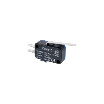
Micro Limit Switch
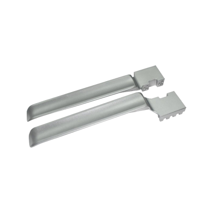
Sliding gate operator limit stopper bracket
Ship or pick up from our office.
Sliding gate operator limit stopper bracket
The gate operator system with a damaged limit stopper bracket can not work properly, and it will soon stop working. Most of the time, the main control board and the motor will be damaged because of this issue and have to be replaced. Sometimes errors come from the limit stopper bracket not working because they are damaged and needs only to be cleaned or readjustment. A sliding gate operator limit stopper bracket is a component that works with limit switches to prevent a sliding gate from over-extending its travel, ensuring it stops at the desired open and closed positions. These limit stopper brackets typically hold magnets or other sensor components that interact with the limit switches on the gate operator's control board. They help maintain the gate's smooth and safe operation by preventing it from hitting obstructions or going off its track. Here's a more detailed explanation: Purpose: The primary function of the limit stopper bracket is to define the boundaries of the gate's movement. It ensures the gate stops at the fully open and fully closed positions, preventing it from over-traveling. How it works: The bracket holds a magnetic or other type of sensor that is triggered when the gate reaches its limit. This trigger sends a signal to the gate operator's control board, which then stops the motor. Components: Bracket: The physical structure that holds the sensor. Sensor: A device (often a magnet) that interacts with the limit switch. Limit Switch: A switch on the gate operator's control board that is activated by the sensor. Importance: Safety: Prevents the gate from hitting objects or going off track, reducing the risk of damage or injury. Reliability: Ensures consistent and reliable gate operation by defining the travel limits. Protection: Protects the gate, operator, and surrounding objects from damage due to over-travel.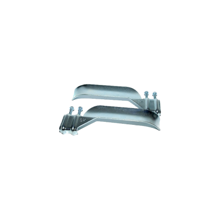
Sliding gate operator limit stopper bracket
Ship or pick up from our office.
Sliding gate operator limit stopper bracket
The gate operator system with a damaged limit stopper bracket can not work properly, and it will soon stop working. Most of the time, the main control board and the motor will be damaged because of this issue and have to be replaced. Sometimes errors come from the limit stopper bracket not working because they are damaged and needs only to be cleaned or readjustment.A sliding gate operator limit stopper bracket is a component that works with limit switches to prevent a sliding gate from over-extending its travel, ensuring it stops at the desired open and closed positions.
These brackets typically hold magnets or other sensor components that interact with the limit switches on the gate operator's control board. They help maintain the gate's smooth and safe operation by preventing it from hitting obstructions or going off its track.
Here's a more detailed explanation:
-
Purpose:The primary function of the limit stopper bracket is to define the boundaries of the gate's movement. It ensures the gate stops at the fully open and fully closed positions, preventing it from over-traveling.
-
How it works:The bracket holds a magnetic or other type of sensor that is triggered when the gate reaches its limit. This trigger sends a signal to the gate operator's control board, which then stops the motor.
-
Components:
- Bracket: The physical structure that holds the sensor.
- Sensor: A device (often a magnet) that interacts with the limit switch.
- Limit Switch: A switch on the gate operator's control board that is activated by the sensor.
- Bracket: The physical structure that holds the sensor.
-
Importance:
- Safety: Prevents the gate from hitting objects or going off track, reducing the risk of damage or injury.
- Reliability: Ensures consistent and reliable gate operation by defining the travel limits.
- Protection: Protects the gate, operator, and surrounding objects from damage due to over-travel.
- Safety: Prevents the gate from hitting objects or going off track, reducing the risk of damage or injury.
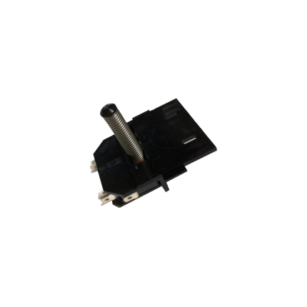
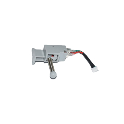
Sliding gate operator limit sensor -Spring
Ship or pick up from our office.
Sliding gate operator limit sensor -Spring
A sliding gate operator limit sensor with a spring mechanism (also known as a mechanical limit switch or spring limit switch) is a common type of sensor used in automatic sliding gate systems to define the gate's fully open and fully closed positions. Here's how it works and what its characteristics are: Purpose of a Limit Sensor: For any automatic gate operator, the system needs to know exactly when the gate has reached its desired open and closed positions. This is crucial for:- Stopping the Motor: Preventing the motor from continuing to run once the gate has reached its limit, which would otherwise cause damage to the gate, the motor, or the track.
- Safety: Ensuring the gate stops precisely where it should, preventing it from hitting obstacles or over-extending.
- Proper Operation: Allowing for features like auto-closing, pedestrian mode, and proper synchronization if it's a dual-gate system.
- Components: A spring limit switch typically consists of:
- A microswitch (an electrical switch that requires very little force to operate).
- A spring-loaded lever, arm, or plunger connected to the microswitch.
- A mounting bracket to attach it to the gate operator or gate frame.
- Mounting: The spring limit switch is usually positioned on the gate operator itself, or on a bracket near the motor.
- Interaction with the Gate:
- On the sliding gate itself, usually along the gear rack or a specific part of the gate frame, two small "stop" tabs or flags are installed – one for the open limit and one for the close limit.
- As the gate moves towards its fully open or fully closed position, one of these tabs/flags will physically contact and push against the spring-loaded lever/plunger of the limit switch.
- This physical contact compresses the spring and activates the microswitch.
- Signal to Control Board: When the microswitch is activated, it sends an electrical signal to the gate operator's main control board.
- Motor Stop: Upon receiving this signal, the control board immediately cuts power to the motor, stopping the gate precisely at that determined limit.
- Physical Contact: The defining feature is that it relies on direct physical contact and force to activate the switch.
- Reliability: Generally reliable as they are a simple mechanical system.
- Durability: Made to withstand repeated physical contact. However, over time, the spring can wear out, lose tension, or the switch itself can be damaged by repeated impacts or debris.
- Adjustability: The position of the "stop" tabs on the gate can be adjusted to fine-tune the exact open and closed positions of the gate.
- Maintenance: May require periodic checks to ensure the spring is intact, the switch is clean, and the "stop" tabs are securely in place and correctly positioned. They can be susceptible to damage from impacts (e.g., if a child's toy or a pet gets in the way of the stop tab).
- Compared to Magnetic Limit Switches:
- Magnetic Limit Switches: These are more common in newer and higher-end gate operators (like many BFT Deimos "Ultra" models). They use magnets attached to the gate and magnetic sensors (reed switches or Hall effect sensors) on the operator. They offer a "contactless" operation, which generally leads to less wear and tear, greater precision, and less susceptibility to environmental debris or physical impact damage.
- Spring/Mechanical Limit Switches: Are typically more cost-effective and simpler in design. They are still widely used, especially in more budget-friendly or older gate operator models.
Sliding gate operators limit sensor -Spring
Ship or pick up from our office.
Sliding gate operator limit sensor -Spring
A sliding gate operator limit sensor with a spring mechanism (also known as a mechanical limit switch or spring limit switch) is a common type of sensor used in automatic sliding gate systems to define the gate's fully open and fully closed positions. Here's how it works and what its characteristics are: Purpose of a Limit Sensor: For any automatic gate operator, the system needs to know exactly when the gate has reached its desired open and closed positions. This is crucial for:- Stopping the Motor: Preventing the motor from continuing to run once the gate has reached its limit, which would otherwise cause damage to the gate, the motor, or the track.
- Safety: Ensuring the gate stops precisely where it should, preventing it from hitting obstacles or over-extending.
- Proper Operation: Allowing for features like auto-closing, pedestrian mode, and proper synchronization if it's a dual-gate system.
- Components: A spring limit switch typically consists of:
- A microswitch (an electrical switch that requires very little force to operate).
- A spring-loaded lever, arm, or plunger connected to the microswitch.
- A mounting bracket to attach it to the gate operator or gate frame.
- Mounting: The spring limit switch is usually positioned on the gate operator itself, or on a bracket near the motor.
- Interaction with the Gate:
- On the sliding gate itself, usually along the gear rack or a specific part of the gate frame, two small "stop" tabs or flags are installed – one for the open limit and one for the close limit.
- As the gate moves towards its fully open or fully closed position, one of these tabs/flags will physically contact and push against the spring-loaded lever/plunger of the limit switch.
- This physical contact compresses the spring and activates the microswitch.
- Signal to Control Board: When the microswitch is activated, it sends an electrical signal to the gate operator's main control board.
- Motor Stop: Upon receiving this signal, the control board immediately cuts power to the motor, stopping the gate precisely at that determined limit.
- Physical Contact: The defining feature is that it relies on direct physical contact and force to activate the switch.
- Reliability: Generally reliable as they are a simple mechanical system.
- Durability: Made to withstand repeated physical contact. However, over time, the spring can wear out, lose tension, or the switch itself can be damaged by repeated impacts or debris.
- Adjustability: The position of the "stop" tabs on the gate can be adjusted to fine-tune the exact open and closed positions of the gate.
- Maintenance: May require periodic checks to ensure the spring is intact, the switch is clean, and the "stop" tabs are securely in place and correctly positioned. They can be susceptible to damage from impacts (e.g., if a child's toy or a pet gets in the way of the stop tab).
- Compared to Magnetic Limit Switches:
- Magnetic Limit Switches: These are more common in newer and higher-end gate operators (like many BFT Deimos "Ultra" models). They use magnets attached to the gate and magnetic sensors (reed switches or Hall effect sensors) on the operator. They offer a "contactless" operation, which generally leads to less wear and tear, greater precision, and less susceptibility to environmental debris or physical impact damage.
- Spring/Mechanical Limit Switches: Are typically more cost-effective and simpler in design. They are still widely used, especially in more budget-friendly or older gate operator models.


